Geology 319 Structural Geology: The Architecture of Earth’s Continental Crust
Study Guide :: Unit 6
Nonorogenic Structures
Overview
At its broadest, nonorogenic structure refers to any geologic structure not caused by orogenic stresses. It therefore describes a wide variety of phenomena, including all primary structures. In this unit we will focus on three important nonorogenic phenomena that we have not yet discussed: intrusive bodies (Lesson 1), glacial deformation (Lesson 2), and landslides (Lesson 3).
Objectives
After studying this unit, you should be able to
- define diapirism and explain the conditions necessary for emplacement of an intrusion.
- describe the different kinds of intrusions (igneous, sedimentary, salt) that can occur.
- describe the stress regimes in which intrusions occur.
- explain the formation of ice thrust complexes, and outline why they are significant for engineering purposes.
- describe the different kinds of landslides and the circumstances under which they occur.
- identify circumstances in which there is a risk of landslides.
Lesson 1: Intrusive Bodies
Note: For this lesson, it is assumed that the student has a basic knowledge of intrusive igneous structures such as dikes, sills, plutons, etc., from an introductory geology course. If you have studied these structures before, but need to refresh your memory, you may find it helpful to study Figure C.11 (Davis, Reynolds, & Kluth, p. 702). If you have not studied this topic before, it is strongly recommended that you look up intrusive igneous structures in an introductory geology textbook before proceeding with the lesson.
When one material is injected into another, the injected material is called an intrusive body (or an intrusion), and the receiving material is called country rock. Intrusive bodies originate through a process called diapirism, which occurs when material has a lower density than surrounding country rock, causing the material to rise buoyantly. The greater the density difference, the greater the buoyant force. Diapirism takes place only if the buoyant force is greater than the strength of the diapiric material and the overlying rocks.
Intrusive materials may be either fluid or solid during the injection or intrusion process. Injection of magma is the most common form of fluid intrusion (producing igneous intrusive bodies); however, water-saturated mud or sand can flow like water and become injected into overlying beds. Solid-state intrusion generally results from movement of material that is ductile and very weak (rheid), and that can flow and intrude the overlying rock under certain conditions. However, diapirism can also occur in stronger material. For example, the frozen top of an igenous pluton may be rammed upwards by the flow of still-molten magma deeper in the rising body. Examples of diapiric material include water-saturated sediment, salt, and of course, magma. Igneous plutons of granitic composition account for more continental mass than any other rock type.
All diapirs started out as weak, low-density material, but not all weak, low-density material forms a diapir. The occurrence of diapirs tends to be determined by controlling structures. Diapirs may occur along fault zones or in the crests of anticlines. Salt diapirs may rise up from particularly thick parts of the source salt bed. Most igneous plutons form above subduction zones. Some igneous plutons form during the main volcanic phase of geosynclinal development, but most form during the orogenic phase. Thus, the location of melting at depth along subduction zones has a lot to do with the location of igneous plutons.
As we have already discussed, intruding material may exist in both fluid and solid physical states.
1.1. Physical States of Intruding Material
Fluid
- Magma can be a mush of up to 90% crystals that are surrounded (coated) by liquid that allows the crystals to slide easily past each other. This mixture can be called a crystal mush or magma slurry. The flow behaviour of this kind of material is not much different than if it were all molten rock.
- The physical state of unlithified sediment under high fluid pressure is a slurry, not unlike a crystal mush, except that the grains are of clastic origin and the fluid is water (very rarely oil). Mud and shale form small pluton-like bodies, but these are rare. It is more common for sand to form small dikes and sills, called sandstone intrusions or clastic intrusions.
Solid
- Ductile Solid-state Flow (Rheid Flow)
Salt diapirs (sometimes called salt domes or salt plugs) are plutons of solid salt that rise from source beds several kilometres below the Earth's surface. The salt plutons may rise vertically for as much as 20 km, and vary in diameter from about 1 km to 30 km. Salt is a weak rock even under room conditions, but it becomes weaker still when subjected to the higher temperatures that result from several kilometres of burial.
The source bed of salt is always a thick (>100 m), complex rock, generally containing many different salt beds, along with interbeds of clay and gypsum, and sometimes limestone and lava. During rheid diapirism of the salt, these beds become complexly folded, perhaps faulted, and undergo ductile deformation that produces cleavage and lineation.
Salt plutons are economically important. Not only have they been mined for salt for over 3000 years (e.g., near the city of Salzburg [or salt mountain] in Austria), but. in some places, they are also responsible for the entrapment of petroleum that has accumulated in the domed rocks above buried salt plugs (similar to the accumulation in antiforms) or in tilted rocks just off their flanks. The Gulf of Mexico, especially the Gulf Coast regions of Texas and Louisiana, contains the largest collection of salt diapirs on Earth, and these diapirs have produced many billions of barrels of crude oil.
- Solid-state rheid igneous diapirs are igneous plutons that were injected in the fluid state, but later remobilized in the rheid state. They occur in complex geological situations where an igneous pluton has been injected into denser volcanic rock. The entire region is eroded, then burial begins again atop the unconformity. When the thickness of post-unconformity sedimentary and volcanic material reaches at least 25 km (especially during an orogeny), the rocks reach temperatures approaching the melting temperature of the original pluton (melting might occur as low as 650°C). The rock material becomes weak at these high temperatures, and rheid diapiric flow of the old pluton may occur, injecting the remobilized pluton through the unconformity and into younger rocks above. Such bodies are commonly called remobilized plutons or sometimes mantled gneiss domes (a dome of gneiss mantled by unconformably overlying rock). They occur only in regions of high-grade metamorphism.
- Solid-state forceful intrusion (brittle intrusion) occurs where the already-frozen top of a pluton is driven upwards by diapiric rise of material below that is still in a fluid or rheid state. This process occurs mostly near the earth's surface, at the top or flanks of igneous plutons, and commonly results in faults and highly fractured zones near the perimeter of such plutons in both the pluton and the country rock.
1.2. The Stress Ellipsoid and Intrusion
Dikes, Sills, and Plutons
Analyses of the ways in which rock masses have stretched or have been displaced during intrusion allow us to interpret the nature of the stress ellipsoid that initiated intrusion. These analyses also lead to the observation that, in some cases, the process of intrusion modifies the ambient stress field, causing second-order structures to form.
Figure 6.1 (Study Guide) shows the stress field that initiates the intrusion of dikes, sills, and plutons (either sedimentary or igneous). The concept of the direction of easiest relief is useful here. This is the direction in which the rock mass will expand, open, elongate, or flow. It is the direction of the S1-axis of the strain ellipsoid, and during strain, it is also the minimum principal stress direction (σ3: the instantaneous minimum principal stress).
Dikes form where the minimum principal stress is horizontal (or nearly so), and the σ1, σ2 plane is subvertical (see Fig. 6.1a). Here, a fracture involving expansion (or dilational separation) develops perpendicular to the σ3 direction, and the dike fluids flow into it as it opens. The plane of the dike is thus the σ1, σ2 plane, but these stress axes could have any orientation within that plane. The fracture may form immediately in advance of the flowing dike, or a dike could simply follow an old dilational fracture.
Sills and laccoliths form where σ3 is vertical and the σ1, σ2 plane is horizontal, becoming the plane of the sill (Fig. 6.1b).
A slightly more complex stress situation (Fig. 6.1c) occurs as a result of the increasing weight of rock with depth. Near the Earth's surface, σ3 is vertical, but as depth (and therefore lithostatic pressure) increase, σ3 becomes horizontal, and either σ1 or σ2 is vertical. Under these circumstances, rising magma forms dikes at depth, but sills or laccoliths form closer to the Earth's surface where the stress conditions are different.
Plutons form where the gravitationally-induced “force of flotation” of fluid or rheid material is the main force. If the horizontal stresses are equal, the diapir will be circular in the horizontal plane (i.e., in map view; see Fig 6.1d and e). If they are not equal, such as during an orogeny, the pluton will be elongate in map view, and its shortest dimension (its width) will be parallel to σ1 (Fig. 6.1f). These stress relationships cause syn-orogenic plutons to be elongate (generally), whereas post-orogenic plutons are more-or-less round.
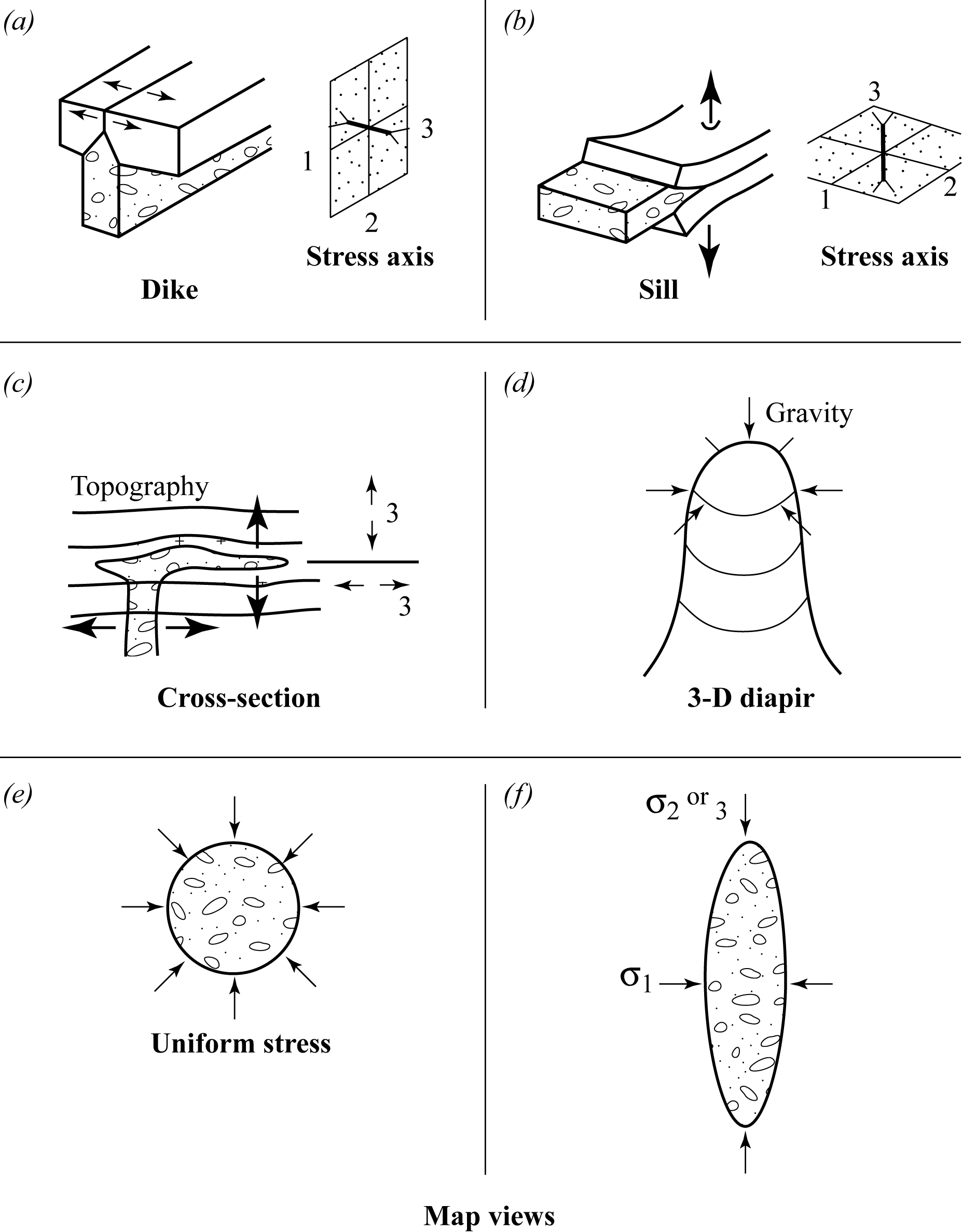
Figure 6.1. Stress fields and intrusions
Second-Order Structures Related to Plutons: Domes, Joints, Dikes and Cauldera
The upward force of a diapir on the overlying rock has two effects: doming of the overlying beds, and stretching of these beds over the dome. If the rocks are being metamorphosed at high enough temperatures, then stretching will be ductile. If the rock is brittle, then it will fracture as it is being domed, and dike emplacement can occur along some of the larger fractures. Two different sets, or swarms, of fractures can form—concentric swarms or radial swarms—depending on how the domal stretching occurs.
The left column of Figure 6.2 shows the case where most of the stretching takes place over the dome. The vertically rising diapir will cause σ1 to be subvertical and to curve upwards (cross-section). The minimum principal stress, σ3, is initially horizontal, but will follow the dip of the stretching beds as they become progressively more domed. The intermediate principal stress, σ2, will be perpendicular to σ1 and σ3, and will result from concentric stretching around the dome (map view). Extensional fractures will develop because of stretching in the σ3 direction (shown by the heavy arrows and the open-dotted zones in the diagrams). These fractures will be parallel to the σ1, σ2 plane (cross-section and map view), resulting in the formation of many millions of concentrically arranged fractures that dip inwards towards the diapir. The fractures that fill with dike material are called cone sheets. Some of these fractures also will undergo normal-fault slip. The upward-domed part of the structure may drop downward, especially if the diapir is an igneous magma into which the overlying rock can sink.
Figure 6.2 (right column) shows the situation where most of the stretching takes place concentrically around the dome (controlling σ3). Here, σ1 will be subvertical as before, but σ2 will follow the dip of the beds. In this case, fractures will develop perpendicular to σ3, in a radial arrangement. A radial dike swarm will form if dikes fill some of the fractures.
Both cone sheets and radial dikes can form in the same dome if the direction of maximum stretching alternates as doming proceeds. In some cases, magma may erupt through these dike swarms and form volcanoes. Most large volcanoes swell and dome to some degree as magma rises, causing concentric and radial fracture sets to form within the volcano itself. If some of these fractures leak lava, small flanking volcanoes will form.
Sometimes large areas affected by concentric fracturing above a magma diapir may founder and sink rapidly, with or without an explosive release of magma and magmatic gases. Quiet, occasional small founderings produce small volcanic cauldera (up to several kilometres across), such as that on Kilauea, Hawaii. Explosive foundering of larger areas (up to 50 km across) produces rare but extremely violent cauldera eruptions: a major one took place in New Zealand less than 2000 years ago. Some small cauldera eruptions, such as that at Mt. St. Helens in 1980, involve explosion, but not foundering.
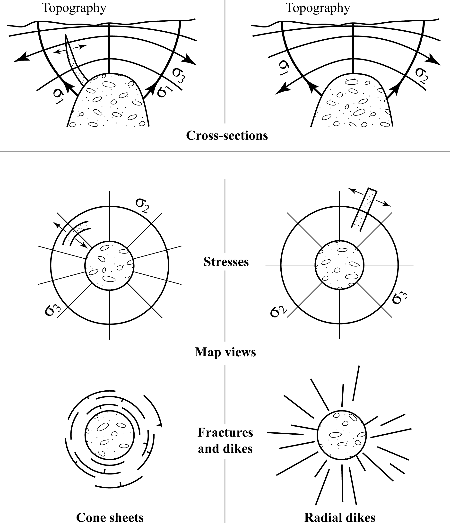
Figure 6.2. Domal stretching and fracture types
Reading Assignment
- Read Davis, Reynolds, & Kluth: “Intrusive Contacts: Magmatic” (pp. 700-703)
Study Questions
- What is diapirism?
- What kinds of materials make up intrusions?
- Why does rising magma tend to form dikes at depth, but forms sills and laccoliths closer to the Earth's surface?
- What is the difference between the stress regime that permits radial dikes to form and that which permits cone sheets to form?
- What are xenoliths?
Lesson 2: Glacial Deformation
A flowing glacier undergoes internal ductile deformation. The rock over which the glacier flows (including unlithified material) undergoes glacial erosion, producing a number of well-known features and landforms such as glacial striations, grooves, and drumlins. Erosion by glaciers can be divided into two broad categories:
- Bedrock material is removed particle by particle. These particles can range in size from microscopic grains to house-sized fragments. Particles are later deposited to form various types of sedimentary materials such as till, glacio-fluvial deposits, glacial-lake sands and clays, wind-blown deposits (sand dunes and loess), and marine deposits.
- Large masses of more-or-less cohesive material are scooped out or scraped off. Such masses are driven for as much as 50 km down ice, then deposited as ice-thrust hills or ridges in which the material has been thrust faulted, folded, and fractured. This process is called glacial deformation, ice thrusting, or glaciotectonics.
2.1. Glaciotectonics
Glaciotectonics takes place where the material being overridden by a glacier is fairly weak. In the most common situation, a weak, porous material, such as sand or till, overlies an even weaker material, such as shale or clay. This material must be unfrozen—otherwise, it would be stronger than the glacier and would not deform—and water-saturated. Analysis of modern glaciers shows that the ground under the front portion of a glacier remains unfrozen. If the underlying material is porous, it becomes saturated with glacial melt water, setting the stage for glaciotectonics.
Glaciotectonics begins when a thrust mass is scraped off a glacier (Fig. 6.3a). Sometimes this leaves a depression (Fig. 6.3b) that may partly fill with water after deglaciation (this is one way in which a glacial lake may form). The thrust mass is dumped down ice, forming an ice-thrust complex (Fig. 6.3b). The ice-thrust complex commonly appears as a hilly area made up of a series of arcuate ridges. The outline shape of an ice-thrust complex may be elongate parallel to ice-flow, it may be parallel to the ridges, or it may be irregular in form. Ice-thrust complexes are typically between 100 m and 200 m thick, and their width ranges from several kilometres to over 50 km. The distance from source (depression) to the complex may be up to 50 km. If glacial erosion continues after ice-thrusting and the upper part of the ice-thrust complex is planed off, no topographic expression remains. It is difficult to recognize eroded ice-thrust complexes, and they are generally not found unless they become dissected by streams or road-cuts.
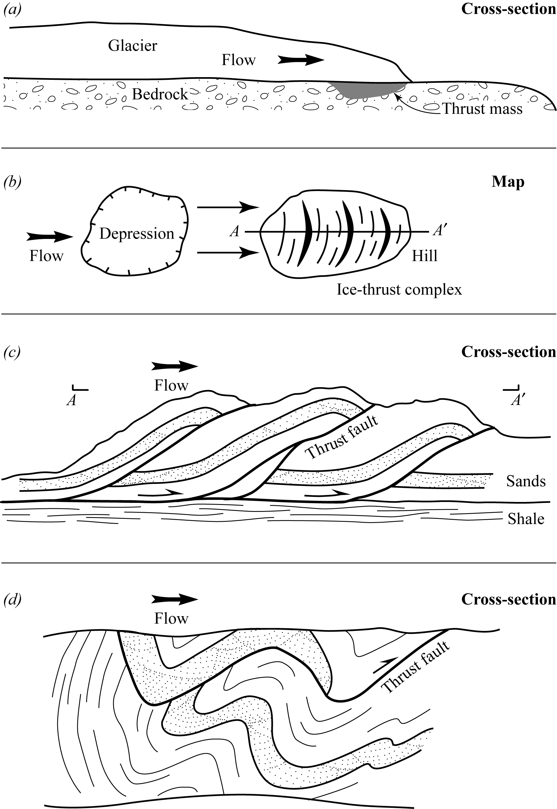
Figure 6.3. Glaciotectonic processes
Ice thrust complexes are internally complex packages of folded, fractured, and thrust-faulted rock that range from the relatively simple situation shown in the cross-section A-A′ (Fig. 6.3b and c), to considerably more complex situations, to a virtually incomprehensible jumble. The cross-section in Figure 6.3d shows a case in which a thrust fault is itself folded. Figure 6.3d could represent a width from several metres to perhaps a hundred metres, but it was actually drawn from a 2 m by 1 m pit dug into an ice-thrust complex about 100 km NW of Saskatoon, Saskatchewan. Individual ice-thrust complexes generally display considerable local variation in their intensity of deformation. The material below the ice-thrust complex remains relatively unaffected, and if beds were horizontal prior to ice-thrusting, then they remain so afterwards (Fig. 6.3c).
Several aspects of ice-thrust complexes can be used as ice direction indicators to interpret the direction of glacier flow responsible for their origin. The relative positions of an ice-thrust complex and its associated depression (if present) can be used to determine the direction of ice flow (Fig. 6.3b). Except where folded, glacial thrust faults dip toward the direction from which the glacier came (or, up-ice; Fig. 6.3c). The dips of fold axial planes can also be used, but this can be tricky, because some folds can dip the opposite way from which the glacier came. In map view, the strikes of faults and folds are generally parallel to the lengths of the ice-thrust ridges, which all tend to be convex in the down-ice direction (Fig. 6.3b).
2.2. Why Study Glaciotectonics?
The topic of glaciotectonics tends to be left out of textbooks because structural geologists have considered it the purview of glaciology, while glaciologists have considered it the purview of structural geology. Increasing recognition of the engineering challenges created by ice-thrust material is leading to some coverage in civil engineering textbooks, however.
Glaciotectonics is important in a variety of ways, some of which are outlined below:
- Ice-thrust complexes affect topography and scenery. Pleistocene glaciation resulted in an unknown number (hundreds at least) of ice-thrust complexes in North America and in parts of Europe and Asia. Most of those that resulted in the formation of hills or ridge complexes have probably been identified. (There are over 30 examples in the northern Great Plains, mainly in Alberta and Saskatchewan.) Some are associated with recognizable up-ice depressions (some with lakes) or up-ice regions of giant glacial grooves or flutes that may be several metres high, tens of metres wide, and several kilometres long.
- An ice-thrust complex is a small-scale version of an orogen. As with all analogies, we don't want to take this one too far, but there are several similarities: both orogens and ice-thrust complexes consist of thrust-faulted and folded material, with dip directions indicative of the direction of movement of the hanging wall body (including ice that has melted). Both may become eroded so that no topographic expression remains. Both are subject to post-formational isostatic uplift. In an orogen, this is due largely to erosion, whereas for a region containing ice-thrust complexes, it is due to melting of the glacier. In fact, ice-thrust masses have at times been mistaken for small outliers of an adjacent orogen. In at least one case, an oil company spent a considerable amount of money drilling into a relatively large ice-thrust complex in eastern Alberta, thinking that potentially oil-bearing Paleozoic limestone would have similar antiformal (and oil-bearing) folds.
- Ice-thrust complexes are important for engineering purposes. Any material that has suffered brittle deformation will be weaker than if it had not been deformed in this way. In ice-thrust complexes, both the thrust faults and the millions of small, glacially-induced fractures weaken the material. The weakened material will not support large buildings or bridges as easily as the undeformed equivalent, nor will it stay up and form the walls of shafts or tunnels. It is more costly to deal with, and can pose serious safety problems if not dealt with properly.
- Ice-thrust complexes may be linked to landslides. A growing body of recent research shows that many landslides in the Canadian plains, especially common along river banks, are controlled partly by previous ice-thrusting. A common situation is for a river to cut into a Pleistocene ice-thrust complex and to expose one or more of the thrust faults. These faults are weak, and the material above them can slide over them toward the river valley. While these landslides can be rapid and locally catastrophic, it is more typical for them to slide only a bit at a time, accumulating many tens of metres of displacement over several thousand years.
Study Questions
- What is glaciotectonics?
- What kinds of materials form glaciotectonic thrust complexes?
- How can thrust complexes provide information about the direction from which a glacier came?
Lesson 3: Landslides
Landsliding is a type of mass wasting, or downslope movement, generally described in introductory texts in physical geology and in physical geography as a surficial process or as a type of erosion. However, landsliding can also be described as a type of normal faulting.
Downslope movements of all types are controlled by gravity: no other stress is required. Because most types of mass wasting involve incohesive material such as soil, loose sand, clay, or glacial till, water also plays a role, either as a lubricant, or as a weakening agent, because water-saturated material is weaker than if it was dry.
Landslides are of two fundamentally different types: slides and slumps. Both occur by the downslope movement of material along more-or-less planar surfaces. Slides are rapid (almost instantaneous), whereas slumps are slow and repetitive.
3.1. Slides
There are two main varieties of slides: rock slides take place in hard, lithified rock, and debris slides take place in unlithified material. In the vast majority of slides, the material breaks up into a rapidly flowing jumble of rock fragments or debris, whose downslope movement is analogous to dumping dry sand out of a bucket onto a sloping surface. The mass sweeps downslope as fast as the force of gravity can take it, and many slides reach velocities exceeding 100 km per hour. The whole event is over within a few minutes, because even large slides flow for only a few kilometres.
Block slides (see Fig. 6.4c) are less common, and form where the slide block does not fragment into a flowing jumble. They can occur in rock or in fairly cohesive unlithified material.
Most rock and debris slides are controlled by pre-existing planes of weakness (or discontinuities) in the material. This is best seen in rock slides (Fig. 6.4a and b). Joints and bedding are the two most common types of discontinuities, although cleavage can be important in metamorphic rocks.
Lithology commonly has a marked control on sliding, and many rock slides occur in a competent rock (e.g., limestone, sandstone, lava, or metamorphosed equivalents) that slides over weaker material (e.g., clay, shale, tuff, or their metamorphosed equivalents). The contact between the competent and incompetent material may form either the base or scarp of the slide mass (Fig. 6.4).
The base of a slide mass can be considered a fault along which sudden, gravitationally-induced slippage occurs. With the exception of block sliding, the slippage is accompanied by complete brecciation of the downward sliding, hanging wall block. Faulting may occur where joints, cleavage, or bedding is the steeply dipping structure. The fault forms the cliff that is left after sliding is complete (Fig. 6.4).
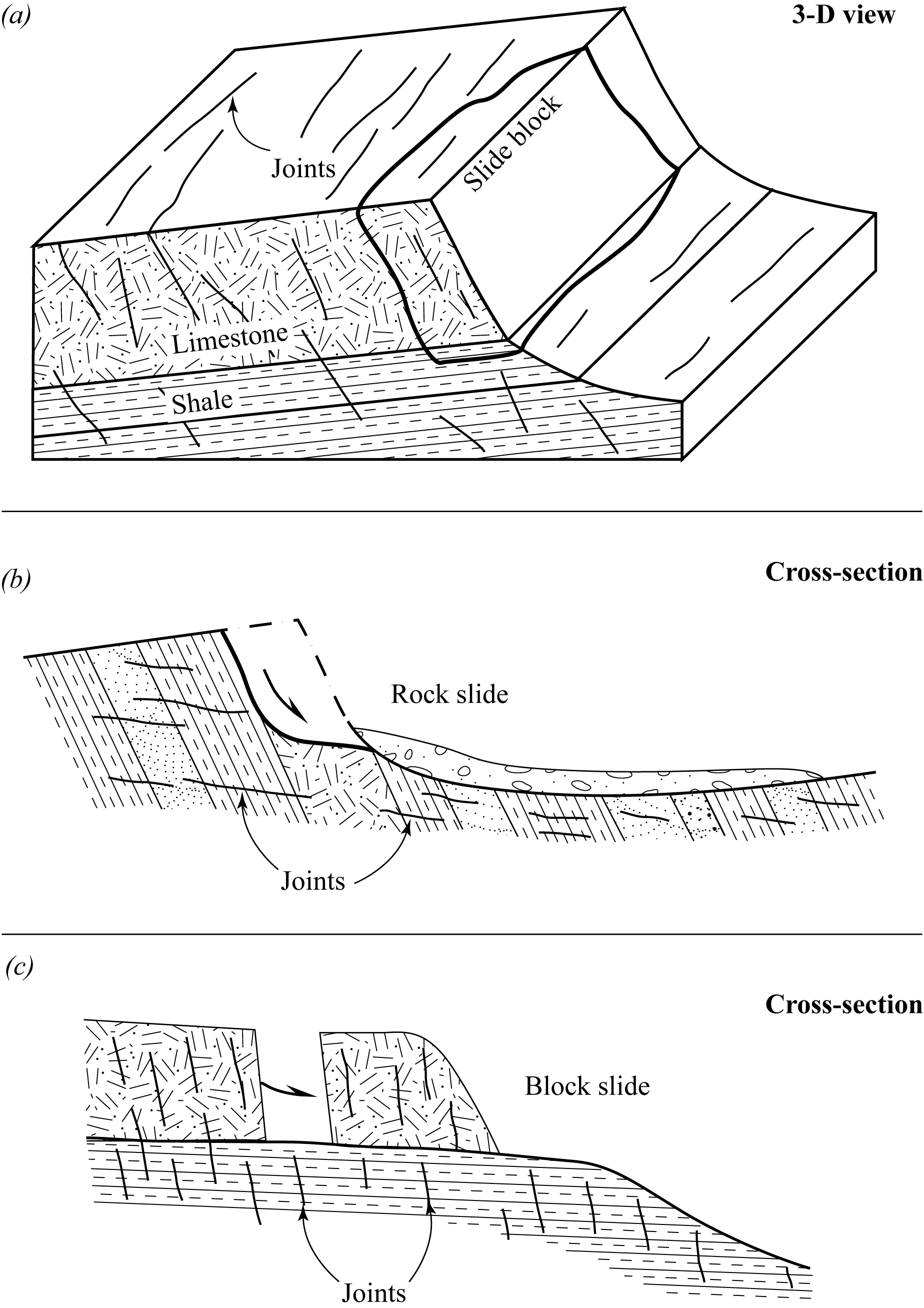
Figure 6.4. Landslides
Rock slides are the most common type of slide, and tend to involve much larger masses of rock than either debris slides or block slides. Some rock slides measure as much as 5 km long, 1 km wide, and 100 m deep. Debris slides are smaller, because unlithified material fragments more easily, and large masses are not required to overcome friction on the slide surface. Block slides are smaller still, because rapidly sliding masses are far more likely to break up than to remain in cohesive blocks. Also, it is thought that block slides move at much slower velocities than rock or debris slides.
Earthquakes commonly trigger rock and debris slides, and every major earthquake in hilly or mountainous terrain results in major mass wasting of one sort or other. The fundamental cause of the landslide, however, is not necessarily the earthquake. Many landslides occur in the absence of earthquakes, and in most cases (earthquake triggered or not), the structure and fabric of the rock is of major importance.
3.2. Slumps
Slumping (Fig. 6.5) is similar to block sliding in that slump masses also remain partly cohesive. Slumping differs from block sliding in that slumping virtually always occurs in unlithified, or only weakly cohesive, material. Slumping is episodic, usually with many faults acting simultaneously to generate small displacements at a time (microscopic to metre scale). Slump masses range from a few tens of metres across to as large as several kilometres; they may be up to 200 m thick.
Slump masses stretch horizontally as they move, and may double or triple in length over hundreds or thousands of years. Horizontal stretching is accomplished by normal faulting.
The many normal faults bound blocks called slump blocks. Topographically, these blocks form slump terraces. Each active fault is partly expressed by a fault scarp (ranging from centimetres to tens of metres high), the largest of which is generally the head scarp at the back of the slump mass.
The front of a slump mass (the toe) moves partly by being pushed from behind, rather than completely by internal normal faulting, so it commonly forms a debris flow. Debris flows may enter rivers, where they may dam or divert the river, or become eroded away.
Most slump masses involve rotational movement on listric normal faults (Fig. 6.5a and b), and the terraces tilt away from the general slope of the slump mass. Recent work suggests that some may also involve block faulting (Fig. 6.5c). Regardless of the style of normal faulting, most large slump masses are controlled by lithology. Typically, an unlithified, porous material such as sand or till overlies a weak, water-saturated material such as clay or shale. The faults cut through the porous cover and flatten in the clay, resulting in a more-or-less horizontal movement along the lithological contact (Fig. 6.5). Small slump masses can form in homogeneous material (sand, till, tuff, or clay-shale) in the absence of stratigraphic control.
A slump mass grows larger with time, not only by horizontal stretching, but also by the production of new head scarps forming behind the crown of the active mass. The slump mass will grow and remain active until the overall topographic slope has been reduced to the point where there is insufficient gravitational potential energy for the slump mass to continue moving. (Understanding this principle is important for engineering purposes).
Earthquakes sometimes reactivate slumping and can initiate new slump masses that otherwise might not have formed, especially in hilly or mountainous regions. In either of these cases, relatively rapid slumping can occur over a limited period of time. Earthquakes are not the major cause of slumping, however. The major causes are topographic relief, the stratigraphic situation, and the force of gravity aided by the presence of water.
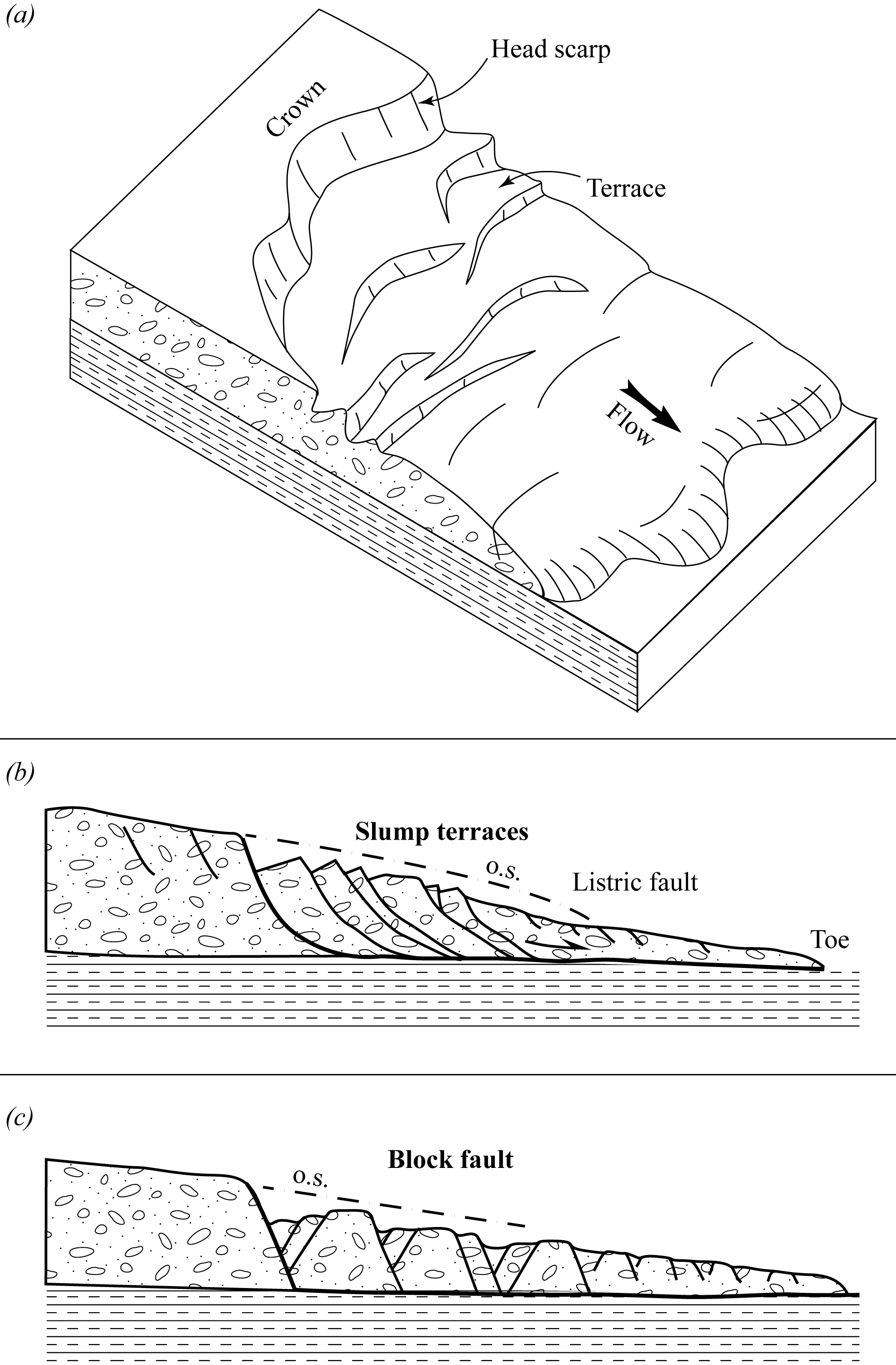
Figure 6.5. Slumps
3.3. Where Not to Build Your House
Slides and slumps can be considerably important to construction projects. In the past, through ignorance, towns have been built at the base of mountains likely to undergo a rock slide. For example, in 1903 the town of Frank, Alberta and many of its inhabitants were buried forever beneath a rock slide from Turtle Mountain. In other cases, people have built buildings, roads, and bridges on moving slump masses, or in locations at risk for landslides, with disastrous results.
As a rule, it is best to avoid building on top of a potential landslide site or in its path. As obvious as this may seem, it is difficult to avoid this risk in many mountainous regions. Therefore, the next best thing is to attempt to reduce the risks associated with building on potentially unstable ground. One approach has been to dig through part of a slump mass and to build on the material below. Unfortunately, this procedure causes an increase in topographic slope for the slump mass, triggering renewed movement—just the opposite of the intended effect! Ways of dealing with some types of slumps have been developed, but they are expensive and are chosen only if no other options exist. For example, a crown region can be cemented or paved up to several kilometres away from the mass, and all water runoff can be controlled through pipes so that the slump mass dries out, making it much less likely to continue moving.
Designing ways to deal with soil conditions that present challenges, such as those found in landslides and ice-thrust complexes, is a growing field of engineering, bringing together geologists and civil engineers into a relatively new field called geotechnical engineering. One important aspect of this relatively new area of awareness is that many countries now have landslide risk maps, showing where recent landslides have occurred and where future landslides may occur. Earthquake-prone regions are more susceptible to landslide risks than are other places, and a large proportion of earthquake deaths are actually due to the landslides triggered by quakes. Areas at high risk for future earthquake damage can be determined by mapping faults along which movement has occurred recently, although perhaps not in living memory or recorded history.
Surprisingly, despite available knowledge of why and where landslides occur, people continue to build in unsafe locations. Part of the problem is that the process of mass wasting is slow on a human timescale. There may be no substantial movement on a slope for decades, which tends to make people complacent about the risks. Where there is pressure for residential development and where the space for that development is expensive and in short supply, the dangers are downplayed, and homes are built where they should not be. Where slopes are too steep, the land will move, but it is difficult to predict exactly when this will happen. Some take this to mean that the risk is low. People often prefer to take the chance that nothing will happen while they live there, rather than giving up on a beautiful view or a large investment.
If you know what to look for, you will be able to spot many examples of homes or other buildings located in unsafe areas. For example, a high ridge on the outskirts of a major western Canadian city has been developed recently for residential use. The slope consists of unconsolidated material, and is sufficiently steep on one side to be a good candidate for landslides. The added mass of homes, infrastructure, people, and their possessions only increases the risk. Some homeowners have seen cracks develop in the plaster of their walls and in concrete only months after moving in, indicating that the slope is moving in small increments.
Another place to look for evidence of unstable ground is along rivers or creeks. The presence of moving water enhances the risk of landslides because it erodes material from the base of the slope (Fig. 6.6a). Once this material is gone, the ground above it is unsupported, and will fall down into the creek (Fig. 6.6b). In older neighbourhoods, homes may be uncomfortably close to the scarp, sometimes with only a sliver of yard left between the house and the scarp. This is not because the homes were built immediately adjacent to the river. Instead, the river has eaten away at the land since the homes were built, and will eventually claim the land on which the homes stand. Anyone looking at the homes now would say that they had clearly been built in the wrong place . . . but 50 years ago, it is unlikely that anyone felt they were risking their home and the well-being of their family by building there.
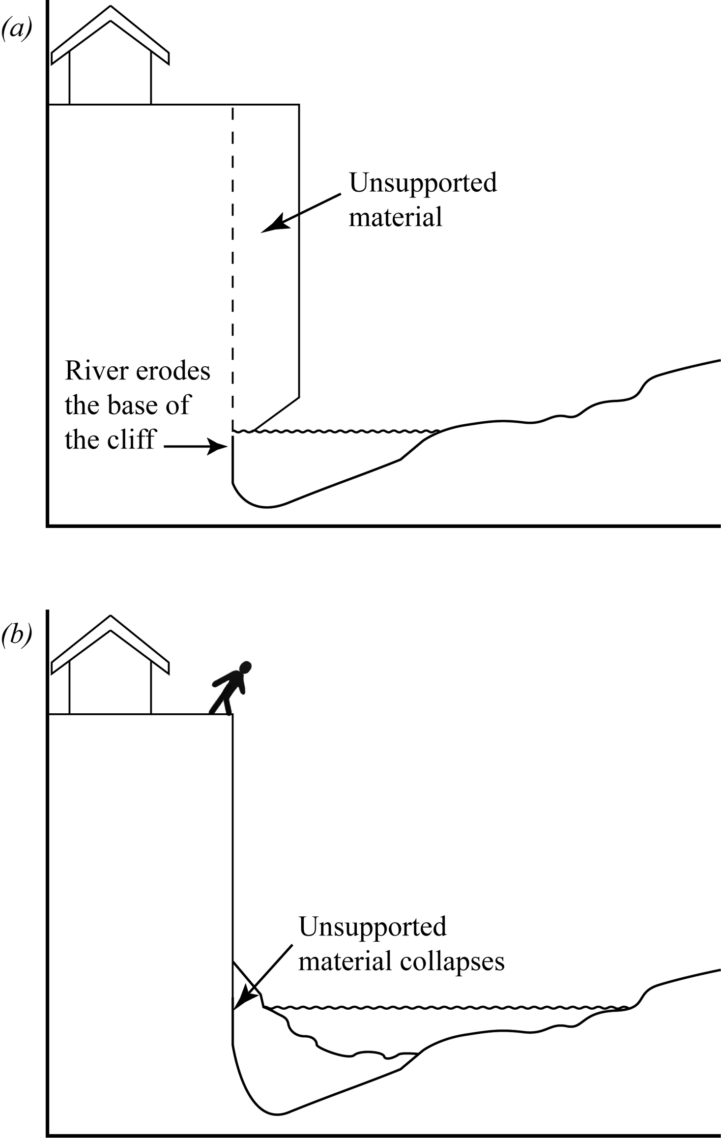
Figure 6.6. Landslides caused by river erosion
Study Questions
- What is the main force that drives mass wasting?
- What is the difference between a slump and a slide?
- What is the influence of lithology on slides?
Assignment 6
You should now complete the theory portion of Assignment 6, which you can find in the assignment drop box. You will submit this assignment to your tutor for grading after you have also completed the lab portion.
Answers to Study Questions
Lesson 1
- Diapirism is the process in which material that has lower density than surrounding country rock rises upward because of its buoyancy. For lower density material to rise, the buoyant force must also exceed the strength of the country rock.
- Intrusions may originate as fluid, including magma and unlithified sediments under high fluid pressure. Intrusions may also originate as solids. Under high pressures and temperatures, salt and igneous plutons will behave as rheids, and will deform in a ductile fashion. It is also possible for non-rheid solids to be intruded. In brittle intrusion, cold plutons located near the Earth's surface can be forced upward by material below that is still in fluid or rheid state.
- At depth, lithostatic pressure is high, so σ1 is vertical. This means it is easier for the country rock to accommodate intrusion by expanding horizontally than by expanding vertically. Horizontal expansion permits a vertical dike to form. Closer to the Earth's surface, the lithostatic pressure is much less, and it is easier for the country rock to expand vertically than horizontally. Vertical expansion permits a horizontal sill or laccolith to form.
- For both cone sheets and radial dikes, the maximum principal stress, σ1, is vertical. The difference is the direction of the minimum principal stress, σ3. Cone sheets and radial dikes form perpendicular to σ3; to form cone sheets, σ3 is directed radially away from the intrusion, whereas to form radial dikes, σ3 is directed tangentially to the intrusion.
- Xenoliths are fragments of country rock that have been incorporated into an intrusion.
Lesson 2
- Glaciotectonics refers to structures and deformation of Earth's crust caused by glaciers. Glaciotectonics ranges from regional-scale isostatic effects (i.e., depression of Earth's crust under the weight of glaciers and then uplift of the crust when the glaciers melt) to deformation of materials on the surface of the Earth as glaciers travel over them.
- Glaciotectonic thrust complexes are formed from weak materials, such as unconsolidated, water-logged sediments. The sediments cannot be frozen, or the glaciers will not be strong enough to deform them.
- One ice direction indicator is the position of a depression from which thrust materials have been removed relative to the position of the thrust complex: the depression is up-ice from the thrust complex. Another indicator is that thrust faults tend to dip in the direction from which the ice came. Finally, in map view, faults and folds tend to be convex in the direction the ice was moving.
Lesson 3
- Gravity is the main force that drives mass wasting.
- The main difference between slumps and slides is that slides take place rapidly, often ending in minutes to seconds, whereas slumps are episodic, and may continue to move over hundreds to thousands of years. Slumps also increase in area over time, because they stretch by normal faulting within the slump and by the formation of new head scarps where the slump originated.
- Lithology influences sliding because weak material often provides a surface for competent material to slide along.