Geology 319 Structural Geology: The Architecture of Earth’s Continental Crust
Study Guide :: Unit 3
Stress, Strain, and Deformation
Overview
Unit 3 examines rock from a materials-science perspective. In this unit, you will learn about how rock behaves under the influence of geologic forces, and the reasons why. In Lesson 1, you will learn that stress, the amount of force applied per unit area, is key to determining the behaviour of rock in response to force. In Lesson 2, you will learn about how rock is deformed, including changes in volume and shape, called strain, and how such changes are quantified. Lesson 3 covers rheology, in which you will learn about the mechanical responses of rock to stress, including rigid, elastic, brittle, and ductile modes of deformation. Lesson 4 covers fractures, the product of brittle deformation, and Lesson 5 covers cleavage and foliation, products of ductile deformation.
Objectives
After completing this unit, you should be able to
- describe brittle, ductile, elastic, inelastic, and rigid responses of rocks to stress, and explain the factors that determine which of these responses will occur.
- describe the different forms that deformation can take and how deformation is measured, including calculating deformation measures when provided with the necessary formulae.
- define stress and strain, and explain what stress and strain ellipsoids represent.
- explain why rocks are stronger under compression than in tension.
- explain what fractures and joints are, including their anatomy, the geological conditions under which they form, and how they can be used to interpret the tectonic history of a region.
- distinguish between cleavage, foliation, and lineation.
- describe the small-scale structure of cleavage, how it develops, and the various forms that cleavage can take.
- describe the outcrop-scale structures formed by ductile deformation.
Lesson 1: Stress
1.1. A Comparison of Stress and Force
Geological structures are generated by a variety of natural forces. The forces acting on any body of rock undergoing deformation are complex. They could include any of the following examples:
- the compression of deeply buried rocks by the force of gravity on overlying rocks
- forces caused by the intrusion of an adjacent body of rising magma
- compression or tension generated by the motion of tectonic plates
Regardless of its cause, the force acting on an object is:
force = mass × acceleration
Weight is a type of force. For example, the downward force that a 10 kg cocker spaniel exerts on a bed of petunias is the product of her mass (10 kg) and the acceleration due to gravity (on average, 9.81 ms−2 on Earth). Her weight would be 98.1 kg·ms−2. The SI unit of weight is the Newton (N), where 1 N = 1 kg·ms−2. The cocker spaniel would weigh less on the Moon, because the Moon has a smaller mass than the Earth, and therefore a smaller acceleration due to gravity: 1.6 ms−2. On the moon, the cocker spaniel would exert a force of only 16 N on a bed of moon petunias.
More important than force for understanding rock deformation, however, is the concept of stress (or pressure), which can be defined as
The relationship between force and stress can be understood by considering what happens when the cocker spaniel's 55 kg owner takes her for a walk on a snowbank. While the human stands on the snow wearing ordinary boots, her force of 55 kg × 9.81 ms−2 = 540 N will be exerted on the snow through the soles of her boots over a surface area of about 0.01 m2. This will cause a stress on the snowbank of 540 N ÷ 0.01 m2 = 54000 Nm−2, which might be enough to cause the snow to compress (deform) under the human (causing her to fall into the snowbank). The cocker spaniel, however, may be able to walk on top of the snowbank without causing enough stress to cause deformation of the snowbank. If the human had been wearing snowshoes, however, the force would be distributed over a larger area, reducing the risk of deformation.
The snowbank example demonstrates two principles that are important to understanding the deformation of natural materials, whether rocks or snow:
- Deformation is determined by stress, not by force. Even a very large force may cause no deformation at all if it is distributed over a wide area.
- Any material resists deformation at low stresses, but there is a threshold value of stress above which the material will deform readily. This threshold is called the strength of the material.
Reading Assignment
- Read Davis, Reynolds, & Kluth: “Force” (pp. 95–101)
- Read Davis, Reynolds, & Kluth: “Tractions” (pp. 101–106)
- Read Davis, Reynolds, & Kluth: “Stress” up to “The Stress Ellipse and the Stress Ellipsoid” (pp. 106–115)
Important Note on Force, Stress and Traction
This Study Guide was written for use with the second edition of Structural Geology of Rocks and Regions. In the second edition, the intensity of a force on a surface is referred to as stress, and is defined as force per unit area (as in section 1.1 above). In the third edition, however, the intensity of a force on a surface is referred to as traction.
Unfortunately, we cannot simply substitute the term traction for the term stress. On page 104 of the second reading in this section (pp. 101–106), you will see a calculation for downward-directed traction (Tdown) due to the weight of overlying rocks on a hypothetical surface. The next calculation is for lithospheric stress (σl), which is the intensity of the force on the hypothetical surface due to the weight of overlying rocks. Both calculations give the same result, 26.5 MPa. The difference is not in the method of calculation, but in how the authors want you to visualize traction and stress. By stress the authors now mean a pair of balanced tractions. For example, when a rock is under compression (i.e., being squeezed), it is because forces on opposite sides of the rock are directed toward each other. These forces produce tractions that are directed toward each other. However, the situation as a whole is referred to as compressive stress.
The distinction between traction and stress is also made in terms of the type of quantity to which each refers. In the second edition (and in this Study Guide) stress is referred to as a vector quantity, which simply means that it has a size (e.g., 26.5 MPa) and a direction (e.g., down). Vectors can be taken apart into components, and stress is resolved into a normal component (acting perpendicular to a surface) and a shear component (acting parallel to a surface). In the third edition, traction is considered a vector that can be separated into normal traction and shear traction. Normal stress and shear stress are still discussed, and they refer to the pair of oppositely directed but equal magnitude tractions. In the third edition, the symbol σn is used to refer to both normal traction and shear traction, and the symbol σs is used to refer to both shear traction and shear stress. The difference is that normal and shear stress are discussed as scalar quantites (i.e., having a size but no direction, where “compression” and “tension” do not count as directions), and stress in general is referred to as a tensor.
A tensor is like a mathematical container for holding vectors. Why is a tensor necessary? If we are referring to a single surface that a force acts upon, the resulting traction can be separated into a normal component vector and a shear component vector, as discussed above. We do this because normal and shear traction have different effects on how a rock is deformed, and, so, it does not make sense to describe them both with a single number. Furthermore, because the shear component is acting parallel to the surface, it can be separated into two additional vector components representing x and y directions (Fig. 3.22, p. 108). That means we need three vectors to provide all of the necessary information about traction on the surface. To keep those together, we use a tensor.
1.2. The Stress Ellipsoid
Regardless of how complex the forces acting on a body may seem, the stress on that body can be expressed in simplified terms as resolved stress. Stress has both magnitude and direction. For example, our person on the snowbank imposed a downward stress (direction) of 5400 Nm−2 (magnitude). Geological forces act in three-dimensional space, and may go in many different directions. Nonetheless, all of these stresses, when added together, can be resolved into (or summarized as) three principal stresses, each oriented at right angles to the other.
The three principal stresses are represented by the stress ellipsoid (Fig. 3.1). The stress ellipsoid is a three-dimensional surface whose axes have lengths determined by the magnitudes of the three principal stresses. By convention,
- the maximum principal stress (the longest axis) is labelled σ1.
- the intermediate principal stress (of intermediate length) is labelled σ2.
- the minimum principal stress (the shortest axis) is labelled σ3.
The stress ellipsoid may have any orientation.
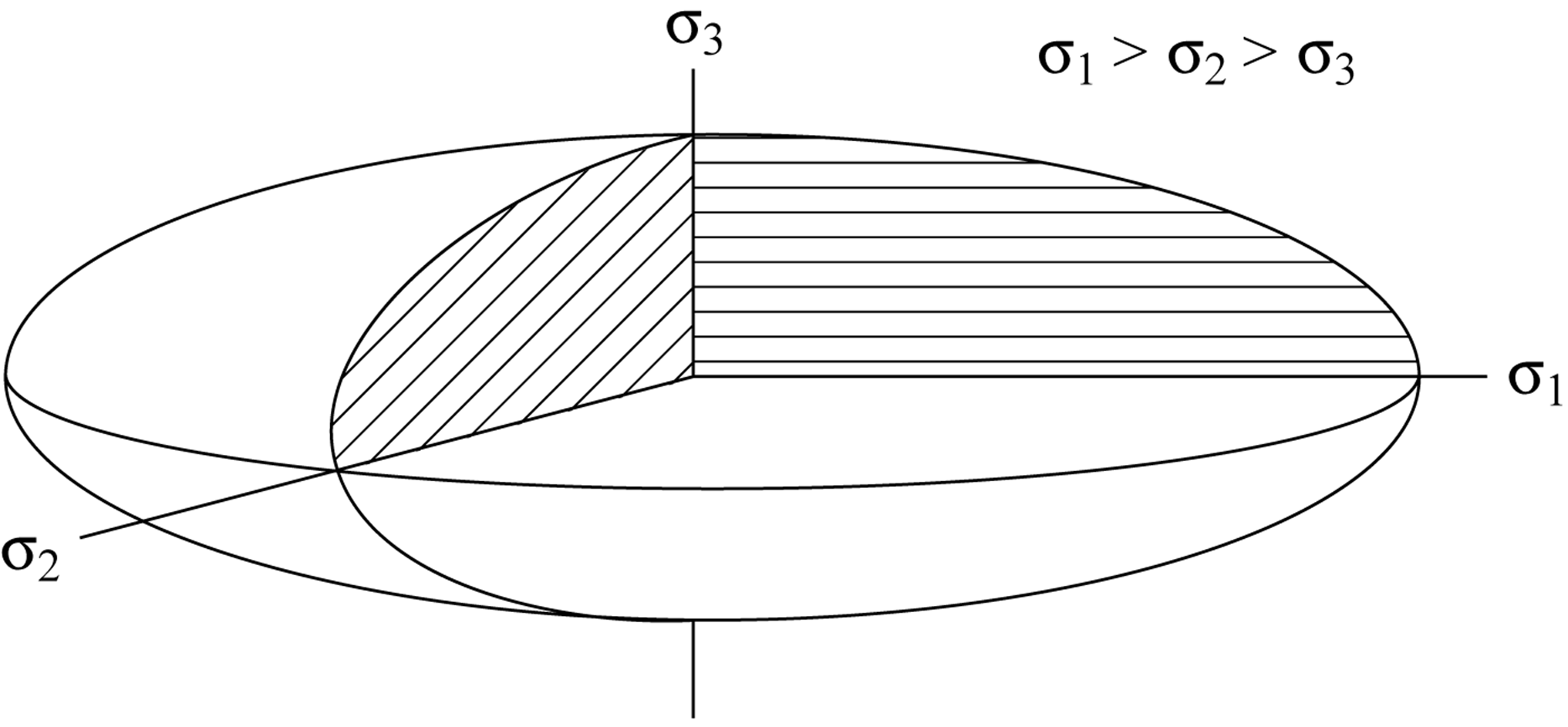
Figure 3.1. Stress ellipsoid
In the most general case of the stress ellipsoid, all three axes have different lengths (i.e., σ1 > σ2 > σ3). In some situations, two of the stresses may be equal (e.g., σ1 = σ2, or σ2 = σ3), so that the resulting deformation is two-dimensional. In the case of the person on the snowbank, the only force is downward, (σ2 = σ3 = 0), resulting in one-dimensional deformation. If all three stresses are equal, then the stress ellipsoid takes the shape of a sphere.
Reading Assignment
- Read Davis, Reynolds, & Kluth: “The Stress Ellipse and the Stress Ellipsoid” (p. 115–116)
Study Questions
- What does it mean to say that forces are vector quantities?
- Which forces are often considered when studying structural geology?
- In words, describe the procedure in the “Museum-Piece Calculation of Traction” (Davis, Reynolds, & Kluth, pp. 102–103).
- What is the difference between normal stress and shear stress?
- What is the purpose of the stress ellipsoid?
Lesson 2: Deformation and Strain
When stress affects a geological body, the result is deformation. Figure 3.2 (below) summarizes the different types of deformation that will be discussed in this section. Deformation is broadly divided into two categories: rigid and non-rigid body deformation. During rigid body deformation, rock may be translated (all points within a body move parallel to each other) or rotated, but there is no change in its size or shape. In contrast, during non-rigid body deformation, also called strain, changes in size or shape do occur. Distortion is a change in shape, while dilation is a change in size. The term dilation applies whether the size increases or decreases.
Pure dilation, a change in size without a change in shape, occurs when all three principal stresses are equal. An example of such equal stresses can be found at the bottom of a swimming pool, where the effect of the weight of the water is spread out equally in all directions (hydrostatic pressure); it also applies to objects on the ground where the weight of the atmosphere affects such objects equally in all directions (air pressure); and also in instances of burial under a load of overlying rock (lithostatic pressure). Lithostatic, hydrostatic, and air pressure have different origins, but all are compressive and affect material equally in all directions. Because of this, they act to reduce the volume of objects, provided the pressure exceeds the compressive strength of the affected material. In a situation where pressure decreases, such as when a balloon is brought from the bottom of a swimming pool to the surface, an increase in volume can occur.
For stress to change the shape of a body, at least one of the principal stresses must be different from the other two, and the difference in stress must be greater than the strength of the material. You can visualize this effect with a sphere made out of modelling clay. If you set the sphere on a table, the air pressure acting on the sphere could be resolved into three principal stresses of equal magnitude. If you were to place your hand carefully on the top of the sphere, you could probably avoid compressing it, while still adding more pressure than air pressure alone. In this case, σ1 > σ2 = σ3, but the difference σ1 − σ3 is still less than the material strength of the clay. As the material strength is not exceeded, no change in shape takes place. If you press down on the sphere hard enough to flatten it into a cookie shape, you have caused σ1 to be much greater than σ2 and σ3, and to be greater than the material strength of the clay. The stress ellipsoid representing the stress exerted on the clay would have a vertical maximum principal stress (σ1). In geology, a stress ellipsoid with horizontal σ1 is more common, such as that caused when rocks of the earth's crust become shortened by horizontal stresses caused by plate collision.
How we label these deformational processes depends on scale. That is, we might use different terms to label a deformation, depending on the size or volume of the rock of interest. Consider a segment of an orogen several kilometres wide, in which a fault has formed. On the scale of the orogen, horizontal shortening caused by the fault is an example of distortion. The rock bodies displaced by the fault have undergone translation. However, the displaced rocks themselves may not have undergone any change in shape. At this smaller scale, although there has been translation, distortion has not occurred. Thus, although strain refers to non-rigid body deformation, on one scale of observation strain can be caused by rigid body deformation on a smaller scale.
Translation, rotation, dilation, and distortion can occur on any scale, but the mechanism that produces the deformation will differ depending on scale. For example, translation can occur as the movement of large fault blocks, as grains sliding past each other, or as sub-microscopic displacements of the crystal structure of mineral grains. (Note: translations on the atomic level cause distortion of the mineral grain as a whole. This is another example of scale-dependent observation and labelling).
Rotation may bend an entire orogen; beds of rock may rotate to form folds; or single grains may rotate in a fault zone.
In the case of dilation, if an entire body of rock becomes microscopically fractured, and the fractures all open minutely, the rock increases in volume. Alternatively, if the rock becomes compacted, grains slide closer together, pore spaces (or voids) become smaller, and the volume of the rock decreases. In either case, dilation will occur in the rock as a whole, but not in the grains that make up that rock. If the grains dissolve to some degree, then the grains will undergo dilation along with the rock.
Distortion may turn geosynclines into orogens; it may distort single plutons from their original intrusive shapes; and individual grains may change shape in a variety of ways (to be discussed later).
Reading Assignment
- Read Davis, Reynolds, & Kluth: “Transformations” up to “Strain” (pp. 34–59)
Note: This reading includes a number of geological examples. It is not necessary to memorize the specific details of these examples.
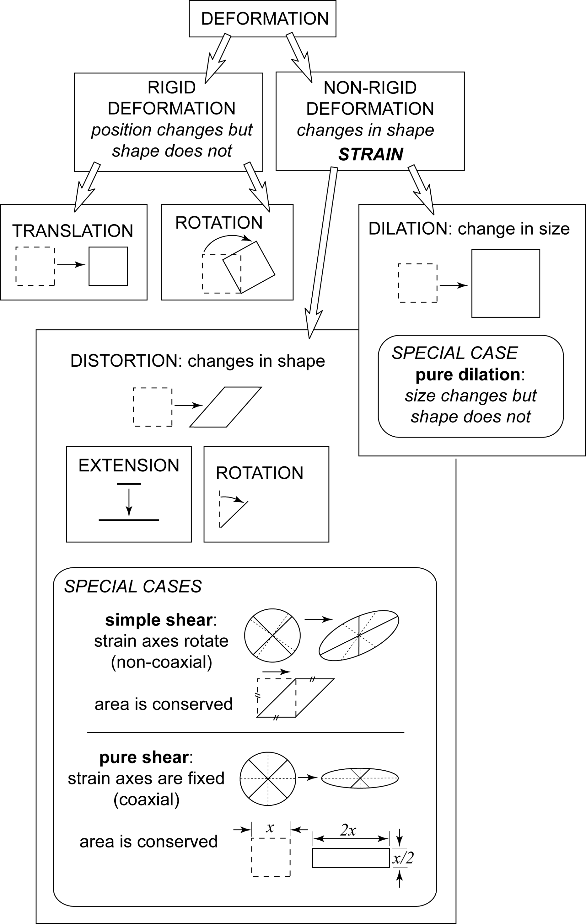
Figure 3.2. Types of deformation
2.1. Measuring Strain
Homogeneous and Heterogeneous Strain
When a rock body deforms, objects (e.g., grains, fossils, or plutons) can shorten or stretch, and the orientation of objects will change. If these changes occur in a uniform manner (i.e., all areas deform by the same amount), the deformation is said to be homogeneous. If the deformation is locally variable, then it is said to be heterogeneous (or inhomogeneous). Homogeneous deformation of a round object (e.g., a grain or pluton) would transform it into an ellipse. The greater the deformation, the flatter the ellipse will become (e.g., Figs. 2.43 and 2.44, Davis, Reynolds, & Kluth, pp. 62–63). Inhomogeneous deformation, on the other hand, might transform the object into a teardrop or dumbbell shape, depending on where the greatest strain took place.
If we look at a large enough mass of rock, all strain presents as inhomogeneous. Nonetheless, it is almost always possible to find small areas in which strain has been at least approximately homogeneous. For example, the strain caused by intrusion of a pluton will be greater in the country rock immediately adjacent to the pluton than in country rock farther away. On the scale of an individual outcrop (say, 10 metres across), however, strain can be nearly homogeneous. It is possible, then, to describe inhomogeneous strain by subdividing it into areas in which homogeneous strain has occurred.
Homogeneous strain is described by analyzing the distortion and dilation of a body of rock. Unfortunately, dilation is frequently impossible to determine, because we usually lack information about the size of the body before dilation has occurred. For this reason, the rest of this discussion will focus on distortion only.
Figure 3.3 shows the geometric outcome of homogeneous strain in two dimensions when the box RSTU is homogeneously deformed into the parallelogram R′S′TU. In this example, neither the height of the object, nor the lengths of the segments RS (R′S′) and TU, change. The lengths of all other lines, however, have either increased (e.g., US′ > US) or decreased (e.g., R′T < RT). Also, the orientations of all lines other than those parallel to the x‑axis of the diagram have been rotated through angle ψ.
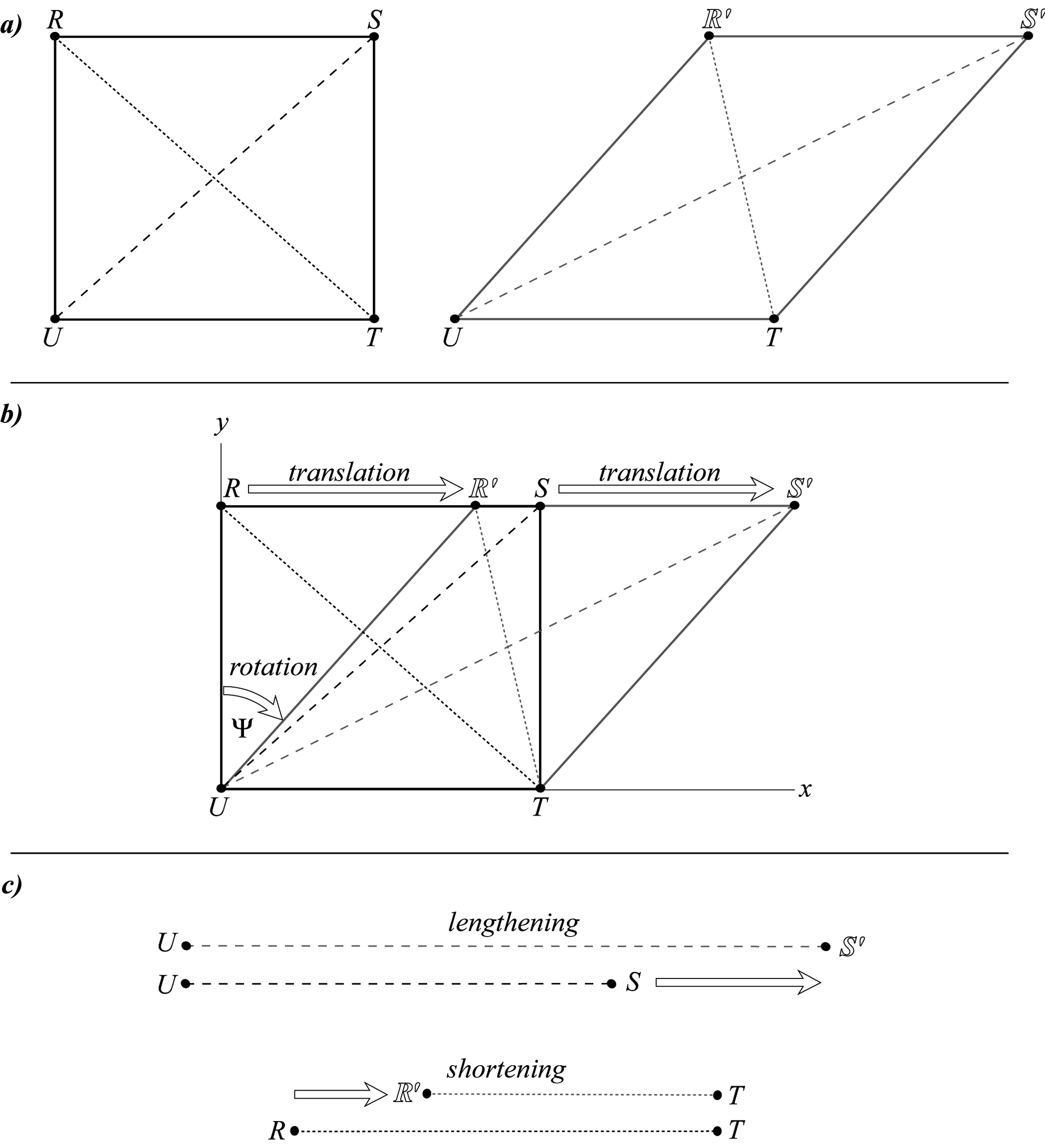
Figure 3.3. Analysis of distortion
Reading Assignment
- Read Davis, Reynolds, & Kluth: “Strain” up to “Describing Changes in Lengths of Lines” (pp. 59–64)
Measuring Changes in Line Length
There are a number of ways to quantify the change in line length as a result of strain. The method we will focus on here is computing the extension, e. If a line stretches, e > 0; if the line shortens, e < 0; if there is no change in the length of a line, e = 0.
Reading Assignment
- Read Davis, Reynolds, & Kluth: “Describing Changes in Lengths of Lines” (pp. 64–65)
Measuring Changes in Angles between Lines
When measuring changes in angles between lines, there are two measurements to consider. The first, angular shear (ψ) describes how a line that was originally perpendicular to a line of interest has deviated from perpendicular. To see what this means, look at Figure 2.49 on page 68 of Davis, Reynolds, & Kluth. In this example, the angular shear along line A is the angle between the original position of line B (dashed line) and its position after deformation (solid line). The angular shear takes a positive sign when the rotation is clockwise and a negative sign when rotation is counterclockwise.
This definition of angular shear makes it sound as though we are describing the rotation of line B, when we are really interested in what happened to line A. One way to make sense of this is to take “angular shear along the line A” to mean “the rotation of line B relative to the axes defined by line A.”
The second measurement we will examine is shear strain, symbolized by the Greek letter gamma (γ). Shear strain describes how points on a line change position as the line is rotated. To gain an intuitive grasp of the meaning of shear strain, pay attention to Figure 2.53 (Davis, Reynolds, & Kluth, p. 72). Notice that γ = 0.5 means that point A is translated to the right by a distance that is half the total width of the object. When γ = 1, point A is translated to the right by a distance equal to the width of the object. In other words, if w is the width of the object, then γ × w is the distance that a point on the undeformed side of the object is translated.
Reading Assignment
- Read Davis, Reynolds, & Kluth: “Angular Shear: Measure of Change in Angles between Lines” to the end of “Shear Strain” (pp. 68–71)
2.2. The Strain Ellipsoid
The strain ellipsoid is a useful concept for visualizing the amount of distortional strain undergone by a body of deformed rock (Fig. 3.4, below). The strain ellipsoid is the shape attained by an originally spherical body that has undergone a homogeneous change in shape.
Perfectly spherical objects are extremely rare in rocks, so both the original sphere and the resulting strain ellipsoid are conceptual idealizations. Nonetheless, the strain ellipsoid allows us to examine the changes in shape of geological bodies of all sizes and original shapes, from microscopic grains to pebbles, to plutons, to entire orogens.
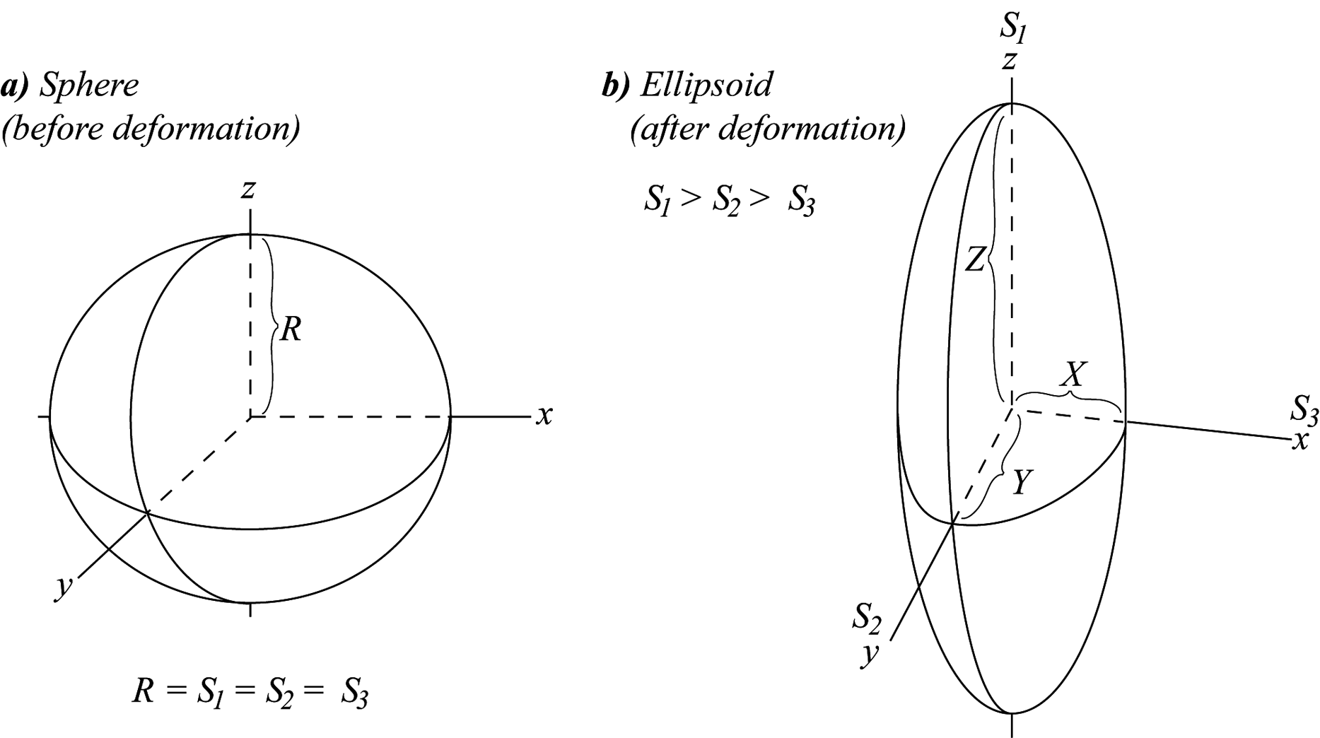
Figure 3.4. Strain ellipsoid
In Figure 3.4a, the original sphere has radius R. The strain ellipsoid has a maximum principal axis of strain S1 an intermediate principal axis of strain S2, and a minor principal axis of strain S3(S1 > S2 > S3). The strain ellipsoid in Fig. 3.4b would be caused by shortening in the x-direction and the y-direction (i.e., along the S2 and S3 principal axes), and elongation in the z-direction (i.e., along the S1 principal axis). We can calculate the extensions undergone in each of the x-, y-, and z-direction using Eq. 2.1 (Davis, Reynolds, & Kluth, p. 64), where lo = R, and the extensions in the x-, y-, and z-directions are ex, ey, and ez, and respectively. The lf in these directions are the lengths X, Y, and Z, respectively. Substituting these variables into Eq. 2.1, we get the following:
Notice that where the ellipsoid is shorter than the original radius of the sphere, the extension is negative, and where it is larger, the extension is positive. The extension can also be expressed as a per cent change by multiplying the extension by 100%. You must specify whether the per cent change is an increase or a decrease; a negative sign can be used to indicate a decrease.
We can also use the axial ratio of the strain ellipsoid as a measure of the strain undergone by an initially spherical object (without having to deal with the original diameter) even if dilation has occurred. The axial ratio is expressed as a triple fraction, X|Y|Z.
Notes about the axial ratio:
- The axial ratio is meant to be a three-part ratio. Do not reduce it to a single value. It is only useful when we can see all three values and imagine the ellipsoid that they would form.
- The axial ratio is simplified by dividing all values by the smallest value. For example, if X = 40, Y = 10, and Z = 25, divide by 10 to get an axial ratio of 4|1|2.5 It is okay for two of the numbers in the axial ratio to be non-integers (i.e., to have numbers after the decimal place). In our example, there is one non-integer value: 2.5.
- The units (e.g., mm, s, g, etc.) are usually as important as the numbers in a computation. They should typically be included from the beginning and carried throughout the calculation. However, in an axial ratio, we leave the units out. This is because the units do not cancel in the three-part ratio, and the axial ratio has meaning without them. The only units constraint is that axial lengths should described by the same unit value to begin with—that is, all measures should be expressed in m or mm, for example. If a calculation were done with X in m, and Y and Z in mm, the axial ratio would erroneously indicate that the ellipsoid was an elliptical pancake standing on its side.
Strain ellipsoids can have an infinite variety of axial ratios, but there are three special cases (see Davis, Reynolds, & Kluth, Fig. 9.80, p. 517):
- Pure flattening (S1 = S2 > S3): shortening along S3 is accommodated by equal amounts of extension in S1 and S2. If the strain is large (S1 = S2 >> S3) the strain ellipsoid will take on the shape of a pancake.
- Pure constriction (S1 > S2 = S3): stretching along S1 is accommodated by roughly equal amounts of shortening along S2 and S3. If the strain is large (S1 >> S2 = S3) the strain ellipsoid will take on the shape of a cigar.
- Plane strain (S1 > S2 > S3, but lf = S2): stretching along S1 is accommodated by shortening along S3 only. There is no distortion along S2.
This means that the volume of the object that undergoes strain will not change, even though the object changes shape.
Rocks deformed according to these special cases develop a layered look as a result of the changes in the shapes of the component materials such as grains, pebbles, and phenocrysts. The alignment of flattened rock components (pure flattening) is an example of a deformational structure called cleavage. Many rocks split more easily in the cleavage direction than in any other (e.g., Marshak & Mitra, Fig. 11-36, p. 239).
Rocks that are deformed mostly by constrictive strain (pure constriction and plane strain) take on an elongated look, much like a bundle of pencils or cigars. This deformational structure is called lineation. As you can see in Figures 9.66, and 9.70 of Davis, Reynolds, & Kluth (pp. 506 & 509), some structural geologists enjoy collecting and admiring elongated pebbles from lineated rocks.
Rocks deformed with or near pure constriction axial ratios will display both cleavage and lineation (as a result of either flattening and constriction combined, or of fault displacement).
Reading Assignment
- Read Davis, Reynolds, & Kluth: “Strain Ellipses” (pp. 73–74)
2.3. Shear
Another important concept, shear, relates to whether or not the strain ellipsoid rotates as stress is applied. Simple shear involves rotation of the strain ellipsoid, whereas pure shear does not (see Fig. 3.2, Study Guide). Simple shear is always two-dimensional. It is a form of plane strain, because length does not change in the S2 direction. Pure shear, on the other hand, can involve either shortening, lengthening, or no change (plane strain) in the S2 direction.
Figure 2.66 (Davis, Reynolds, & Kluth, p. 83) shows simple shear and pure shear in two-dimensional progressive deformation sequences, with flattening shown at 25%, 30%, and 40%. Observe that with simple shear, the strain ellipse rotates as strain progresses, but with pure shear, the axial directions remain constant.
Study Questions
- True or false: Rotation and translation are types of rigid body deformation, but distortion and dilation are not.
Calculate the extension, e, for each axis of the strain ellipsoid shown in Figure 3.4 (Study Guide). Use the following values in your calculation:
R = 20 cm, X = 10 cm, Y = 15 cm, Z = 30 cm.
- Using the values from the previous question, calculate the axial ratio for the strain ellipsoid.
Lesson 3: Rheology
Rheology is the study of the physics of deformation, particularly the mechanical response of a material. In this lesson we will look at four general responses to stress: rigid, elastic, brittle, and ductile.
A rigid body does not change size or shape, nor does it break. There is no truly rigid material, however. Even the strongest material undergoes minute strain under small stresses.
Elastic material undergoes distortion and dilation when subjected to stress, but when the stress is released, the body regains its original size and shape. That is, the deformation is not permanent. Rubber bands and tennis balls are examples of materials that undergo elastic deformation. Many objects that appear rigid are actually elastic, but deform so slightly that the distortions are not readily apparent. For example, if you strike a rock with a hammer, the hammer will bounce back. The bounce occurs because of elastic recovery of distortions in the rock. The harder the impact, the greater the distortion, and the greater the bounce. Geologists are very careful to stand aside of their hammer strike, because the bounce of the hammer may be enough to cause injury.
A brittle material breaks under stress. Careful observations and experimentation have shown that brittle deformation is preceded by a certain amount of elastic deformation. This fact is very important in the discussion of earthquakes.
A ductile material is permanently deformed by stress, but it does not break into pieces. Clay is an example of a ductile material. Ductile materials deform continuously, and undergo increasing distortion as long as a constant deforming stress is applied. The behaviour of ductile materials has been likened to the behaviour of liquids flowing down a slope under gravity, so ductile solids are commonly said to be undergoing fluid flow. Rocks that have undergone a large amount of ductile or solid-state fluid-like flow are often called rheids, from rheology (e.g., Davis, Reynolds, & Kluth, Fig. 3.69, p. 145).
The way in which a material will deform depends both on the inherent nature of the material itself and on the conditions imposed upon the material. From deformation experiments and field observations of deformed rocks, geologists have identified a number of conditions that determine how materials deform. Important conditions include temperature, lithostatic pressure, water content, and strain rate.
- Temperature: Rocks become ductile under high-temperature conditions, even though they may have been brittle while cold. Furthermore, rocks become weaker as temperature increases, so less force is required to cause ductile strain as the temperature rises. For example, limestone does not melt until it reaches a temperature of over 1000°C, but at 600°C it is only half as strong as it is at 300°C. Taffy is a well-known substance that illustrates this point. If you try to bend taffy after it has been refrigerated for a few hours, the force may snap it into pieces. On the other hand, if you try to bend taffy after it has been in the warm sun or in someone's pocket for awhile, it will deform easily.
Lithostatic (or confining) pressure: Confining pressure acts like a tensor bandage. It retards brittle failure and makes it more difficult for ductile deformation to occur. Figure 3.58 (Davis, Reynolds, & Kluth, p. 137) shows the progression from left to right of increasingly ductile deformation with increasing confining pressure on a sample of limestone. Table 3.4 (Davis, Reynolds, & Kluth, p. 138) shows that as the confining pressure increased from 28 MPa to 103 MPa to 207 MPa, the differential stress at failure (i.e., the stress required to cause failure) increased from 124 MPa to 318 MPa to 552 MPa. (Note: If you are curious about experimental rock deformation, see Davis, Reynolds, & Kluth, “Conducting Deformation Experiments in the Laboratory,” pp 128–138.)
If increasing temperature weakens rocks and causes more ductile deformation, but the straight-jacketing effect of increased pressure strengthens rocks, then it would appear that the burial of rocks results in opposing effects. It turns out, however, that for any given depth within the earth, the temperature effect is greater than the pressure effect, so rocks become more ductile with depth.
- Water content: The more water rock contains, the more brittle the rock.
- Strain rate: The faster deformation occurs, the more brittle the rock.
The interaction between environmental conditions and rock type results in a complex array of deformational responses to stress. In fact, a body of rock may deform by both ductile and brittle processes at the same time, although one type of deformation may predominate as rocks first become more deeply buried in a geosyncline, then later become unroofed by erosion and isostatic rebound. We commonly use the phrase ductile-brittle transition in reference to this complex interplay of deformational processes. Experimental and field studies both indicate that the ductile-brittle transition commonly occurs at depths of just a few kilometres. However, because earthquakes can occur as deep as 700 km, and earthquakes are caused by brittle failure, we know that brittle deformation can occur deep within the earth under the right conditions.
Reading Assignment
- Read Davis, Reynolds, & Kluth: “Evaluating Mechanical Behavior During Testing” (pp. 138–146)
Study Questions
- The marble bench in Figure 3.69 (Davis, Reynolds, & Kluth, p. 145) has a low temperature compared to rocks in the interior of the Earth, and it is subject to only negligible confining pressure by the atmosphere. Given the low temperature and low confining pressure, why has the marble sagged (ductile deformation) rather than breaking in two pieces (brittle deformation)?
- Why was it necessary for Cobbold to use very weak materials such as loose sand, Silly Putty, and honey to successfully model the deformation of Earth's crust and mantle?
Lesson 4: Fractures: Products of Brittle Deformation
Fractures form as open cracks by brittle deformation. They form mainly in rocks that are fairly cool at the time of fracturing (mostly those below 300°C). In its broadest sense, the word fracture describes all brittle deformational features in rocks, including large brittle faults, small cracks with only slight or no displacement, and microscopic cracking within grains and along grain boundaries. In this section, however, we will restrict the discussion to outcrop-scale features that display little or no discernible slip. Such fractures, called joints, are important as the locus of hydrothermal mineral deposits, as well as for engineering purposes, because they weaken rock.
Reading Assignment
- Read Davis, Reynolds, & Kluth: “Definitions and Distinctions” (pp. 193-201)
- Read Davis, Reynolds, & Kluth: “A Detailed Look at Individual Joint Surfaces” (pp. 204-212)
- Read Davis, Reynolds, & Kluth: “Example of Columnar Jointing” (pp. 212-213)
- Read Davis, Reynolds, & Kluth: “Joint Patterns in Plutons as Regional Stress Gauges” (pp. 244-246)
Study Questions
Please refer to the readings above (Davis, Reynolds, & Kluth) to complete the following fill-in-the-blank exercise.
Joints are reasonably continuous and through-going planar fractures, commonly on the scale of ______________ in length, along which there has been imperceptible ______________ movement more or less ______________ to the fracture surface. Joints are products of ______________, and they form when the ______________ strength of stressed rock is exceeded.
In most cases, the opening that is accommodated by jointing is nearly ______________.
Overall, we think of joints as structures that permit minor structural adjustments to take place as the regional rock bodies within which they are found are forced to change size or shape. The changes are in response to such actions as ______________ and ______________, ______________and ______________, ______________ and ______________, and ______________.
As families of fractures, joints commonly display ______________ (Figure 5.6) and often show striking symmetry.
A given outcrop area or region of study is typically marked by more than one ______________ of joints (Figure 5.6), each with its own distinctive ______________ and ______________.
Some joint-like fractures are actually ______________, which in effect are ______________.
In trying to determine whether a given fracture may be the product of shearing, we also look carefully for the presence of ____________ (Figure 5.10), products or shearing movement parallel to the fracture surface.
Certain fractures do not qualify as joints, nor do they qualify as conventional shear fractures. Within fault zones, for example, rocks may be ______________ along apparently nonsystematic, extremely closely spaced fractures. The ______________ of the fracturing is ______________ than what is reasonable for ordinary jointing and shear fracturing. Furthermore, the regularity of ______________ and ______________ of fracture surfaces, so typical of jointing and shear fracturing, is absent.
The ornamentation expected in an ideal joint face is subtle but elegant. First, there is the ______________ of the fracture, also referred to as the ______________. This is the very spot where fracture propagation begins.
The ______________, also known as ______________, can be thought of as marking that reflects the front (tip line) of the propagating fracture at different points in time.
The ______________ are feather-like markings that reveal the actual propagation paths.
- Why do columnar joints form? What do the horizontal bands on columnar joint faces tell us about their formation?
- How can joints be used to understand the tectonic history of a region?
- What are shatter cones? Explain how shatter cones can be used to find the location of a stress impact?
Lesson 5: Cleavage and Ductile Deformation
Some rocks tend to split along uniform surfaces, such as into plates or slabs. Although joints can cause a rock to break along uniform surfaces, such a break may not be the result of a loss of cohesion (i.e., a pre-existing crack). In fact, it most commonly occurs because of the alignment of platy minerals in the rock, called cleavage. The rock is weaker in the direction in which the minerals are aligned because it is easier to separate the crystals from each other than to break the crystals themselves. Cleavage is formed by the alignment of some or all of the materials in a rock, and is caused by ductile compression or shortening of the rock. Cleavage forms in rocks undergoing metamorphism (mostly above 300°C) and pervades the entire internal body of the rock more-or-less homogeneously at the hand-specimen or outcrop scale.
The alignment of minerals that causes cleavage in a rock is frequently called foliation. This is the terminology you are likely to find if you look up this topic in an introductory textbook. Davis and Reynolds, however, use the term cleavage to refer to the alignment of platy minerals in the rock and to the tendency for rocks to split along uniform surfaces. Foliation is used as a general term for any sort of alignment in the fabric (i.e., the three-dimensional texture) of a rock. For example, foliation can include primary flow fabrics in igneous rocks, such as the stretching of vesicles in a basalt flow. In this discussion, we will use terminology as used by Davis and Reynolds in the textbook.
Cleavage has a domainal structure. This means that a rock with cleavage will have alternating zones, or domains in its fabric (see Fig. 9.6, Davis, Reynolds, & Kluth, p. 467). Cleavage domains consist of aligned platy minerals. Microlithon domains, on the other hand, consist of crystals that are often equigranular (i.e., stubby or blocky), and which lack a preferred orientation.
The domainal structure of cleavage is the basis of a classification system for cleavage. If the domains are too small to see with the naked eye, the cleavage is called continuous cleavage. If the domains are visible without a microscope, then the cleavage is called disjunctive cleavage. These classes are further subdivided as follows:
Continuous cleavage (domains are not visible to the naked eye)
- High proportion of platy minerals (see Davis, Reynolds, & Kluth, p. 468)
- slaty cleavage, phyllitic cleavage, schistosity (in order of increasing grain size)
- cleavage domains contain mica
- microlithon domains contain quartz and feldspar
- Low proportion of platy minerals. Examples:
- gneiss: (pronounced “nice”) visible grains, often with layering of dark and light minerals
- flattened-fragment cleavages: in rocks bearing large fragments such as pebbles, boulders, lapilli (e.g., flattened-clast conglomerate)
Disjunctive cleavage (domains are visible without the aid of a microscope)
- Crenulation cleavage (see Davis, Reynolds, & Kluth, pp. 469-470, 474-475)
- tiny folds are created in pre-existing continuous cleavage
- cleavage domains contain mica
- microlithon domains contain quartz and feldspar
- Spaced cleavage (see Davis, Reynolds, & Kluth, pp. 469, 475)
- cleavage domains consist of clay- and carbon-rich “partings”
- develops in folded sedimentary rocks
- microlithons lack pre-existing cleavage
Reading Assignment
- Read Davis, Reynolds, & Kluth: “Strain Significance of Cleavage” up to “Dissolution Removal of Fossils” (pp. 475-484)
- Read Davis, Reynolds, & Kluth: “Foliation” (pp. 492-500)
- Read Davis, Reynolds, & Kluth: “Lineation” (pp. 500-511)
Study Questions
- Most cleavage is caused by shortening that is perpendicular to the cleavage plane. This shortening is accompanied by a loss of volume caused by pressure solution. What is pressure solution?
- Much thought has been applied to determining how alignment of grains occurs. Mechanisms include grain rotation, ductile change of shape of individual crystals, and directional crystallization. What is directional crystallization? What are pressure shadows?
- What did Beutner (1978) conclude about the grain alignment of chlorite?
- How did Gray and Durney (1979) explain the development of crenulation cleavage?
- What are stylolitic surfaces?
- What is the difference between primary foliation and secondary foliation? Give examples of each.
- The elongation of pebbles and minerals to form lineations is closely linked to the origin of cleavage. In fact, these lineations lie within the plane of the cleavage in which they form, in the same way that your fingers lie in the plane of your hand. In practical terms, how can you tell the difference between lineation and foliation?
Assignment 3
You should now complete the theory portion of Assignment 3, which you can find in the assignment drop box. You will submit this assignment to your tutor for grading after you have also completed the lab portion.
Answers to Study Questions
Lesson 1
- To say that forces are vector quantities means that forces are always applied in a direction. For example, you might push down or pull up. When it is necessary to describe forces with numbers, the force always comes with a magnitude (size) and a direction (e.g., 40 Newtons downward).
- The forces most often considered in structural geology are the force of gravity (a body force) and the force of one tectonic plate on another (a contact force).
- The objective of the “Museum-Piece Calculation of Traction” is to find out how much stress the granite block imposes on the marble column. Since stress is the force applied over a particular area, two questions must be answered:
- How much force does the granite block apply?
- Over what area does it apply that force?
The force applied by the granite block is a result of gravitational attraction between the granite and the Earth. The magnitude of the force depends on the mass of the granite block, which is a function of the volume of the block (something we can measure) and its density (found in a reference book). The force due to gravity on the granite block is the product of its mass (which we have just calculated) and the acceleration due to gravity (a known constant, ~ 9.8m/s2). The area over which the force is applied is the area of the circular end of the marble column. (You could figure this out with a piece of string and a little bit of geometry if you did not have Fig. 3.15 handy.) Now you can divide the force by the area to calculate the stress on the marble column.
Note: If you were curious about how much stress the entire sculpture applied to the floor, you could calculate the mass of the marble column as you did with the granite, add the two masses together, and multiply the total by the acceleration due to gravity. You would divide this force by the same area you used the first time, the area of the circular end of the marble column.
- The difference between normal stress and shear stress is the direction in which the stress is applied. Normal stress is applied at right angles to a surface. When you stand on a floor, you are applying normal force to the floor. Shear stress is applied parallel to a surface. When you step on a rug and the rug moves out from under you, it is because your foot applied a force parallel to the surface of the rug.
- The stress ellipsoid is a tool for visualizing, summarizing, and calculating the stresses acting on a point. It is convenient because even if there are many sources of stress acting on a point, the net effect of those stresses can be represented by the three principal axes, arranged at 90° to each other. This is true regardless of how many stresses there are to consider, or how many directions they represent. Once the three principal axes are defined, the stress acting in any one direction is represented by the length of a line drawn from the centre of the ellipsoid to the edge of the ellipsoid in the direction of interest. A stress ellipse is a two-dimensional slice of the stress ellipsoid. The stress ellipse must contain any two of the three principle axes. Therefore, in any stress ellipsoid there are three stress ellipses.
Lesson 2
- True.
Principal axis S3: ex = −0.5 (shortened by 50%)
Principal axis S2: ey = −0.25 (shortened by 25%)
Principal axis S1: ez = 0.5 (lengthened by 50%)
Lesson 3
- The marble bench has sagged rather than breaking because the stress due to the force of gravity acting on the bench is small compared to the strength of the marble, and the stress has been applied over a long period of time. A larger stress applied suddenly (e.g., from a sledge hammer) would cause the marble to break (brittle deformation).
- Cobbold used materials that were very weak compared to the rocks that make up the Earth's crust and mantle to account for the stress contributed by gravity. The great size of the rocks being modelled (i.e., whole mountain ranges) means that the rocks can deform under their own weight in addition to deformation due to plate tectonic collisions. The weak materials also account for Cobbold's application of stress over a very short duration compared to the millions of years actually required for continental collisions and mountain building.
Lesson 4
Joints are reasonably continuous and through-going planar fractures, commonly on the scale of centimetres in length, along which there has been imperceptible “pull apart” movement more or less perpendicular to the fracture surface.
Joints are products of brittle failure, and they form when the tensile strength of stressed rock is exceeded.
In most cases the opening that is accommodated by jointing is nearly microscopic.
Overall, we think of joints as structures that permit minor structural adjustments to take place as the regional rock bodies within which they are found are forced to change size or shape. The changes are in response to such actions as burial and compaction, heating and cooling, uplift and subsidence, and landscape evolution.
As families of fractures, joints commonly display systematic preferred orientations (Figure 5.3) and often show striking symmetry.
A given outcrop area or region of study is typically marked by more than one set of joints (Figure 5.3B), each with its own distinctive orientation and spacing.
Some joint-like fractures are actually shear fractures, which, in effect, are microfaults.
In trying to determine whether a given fracture may be the product of shearing, we also look carefully for the presence of slickenlines (Figure 5.10), products of shearing movement parallel to the fracture surface.
Certain fractures do not qualify as joints, nor do they qualify as conventional shear fractures. Within fault zones, for example, rocks may be pervasively shattered along apparently nonsystematic, extremely closely spaced fractures. The density of the fracturing is much greater than what is reasonable for ordinary jointing and shear fracturing. Furthermore, the regularity of orientation and spacing of fracture surfaces, so typical of jointing and shear fracturing, is absent.
The ornamentation expected in an ideal joint face is subtle, but elegant. First, there is the point of origin of the fracture, also referred to as the point of initiation. This is the very spot where fracture propagation begins.
The ribs, also known as undulations, can be thought of as markings that reflect the front (tip line) of the propagating fracture at different points in time.
The plumes are feather-like markings that reveal the actual propagation paths.
- Columnar joints form because lava shrinks as it cools. The columnar joints are fractures that represent the volume lost upon shrinkage. The horizontal bands on the faces of columnar joints (Fig. 5.35, Davis, Reynolds, & Kluth, p. 213) represent discrete fracturing events. This means that the columnar joint did not form all at once, but that as the rock cooled, the fracture progressed downward in increments shown by the horizontal bands.
- Uplift causes the Earth's crust to be stretched. When the tension in the crust is greater than the strength of the rocks, then brittle failure occurs in rocks that are near the surface, resulting in joints. Joints provide information about the tectonic history of a region because joints are oriented perpendicular to the least principal stress. Therefore, the orientation of the joints tells us about the direction in which stresses were applied. The principle of cross-cutting Relationships can be applied to multiple phases of jointing to understand the relative order in which the stresses were applied.
- An impact creates a particular kind of fracturing called a shatter cone. In three dimensions, shatter cones resemble ice-cream cones. The shatter cones may be nested within each other the way ice-cream cones are nested when they are stacked for storage. Shatter cones can help us find the location of an impact because the point of the cone is formed in the direction of the impact. If enough data from the orientation of shatter cones are collected, and the orientations are projected toward the origin of each shatter cone, then (ideally) the projections should converge on the locus of impact. In reality, this process may be complicated by geological processes that changed the orientation of the shatter cones since the time of the impact.
Lesson 5
- Pressure solution or pressure dissolution refers to the fact that an increase in pressure will cause some minerals to dissolve. Grains can be reshaped if only part of the grain is dissolved.
- Directional crystallization means that new crystal growth is controlled by the stresses acting on the rock, and therefore new growth will yield minerals aligned with the cleavage. An example of directional crystallization is pressure shadows. Pressure shadows develop around stronger grains that are resistant to deformation (e.g., pyrite, feldspar, quartz). Low pressure zones form next to these grains where surrounding minerals have not draped completely around the resistant crystals. Minerals that have been dissolved by pressure elsewhere can recrystallize in these low pressure zones. The low pressure zones are oriented parallel to the cleavage (Fig. 9.24, Davis, Reynolds, & Kluth, p. 479).
- Beutner concluded that the chlorite grains (a type of mica) showed a preferred alignment because the pressure solution had selectively dissolved away parts of the crystals in the direction in which the rock containing the crystals was being shortened (Fig. 9.25, Davis, Reynolds, & Kluth, p. 480).
- Crenulation cleavage forms when pre-existing cleavage buckles into small wavy folds (see Fig. 9.26, Davis, Reynolds, & Kluth, p. 481). With continued shortening, the limbs of the buckled waves become steeper and steeper, and eventually develop into cleavage domains. Pressure solution may eventually result in the complete disappearance of the fold limbs.
- Stylolitic surfaces form as a result of pressure solution. The stylolitic surface itself is a jagged series of teeth and cones that are oriented parallel to the direction of greatest principle stress (see Fig 9.27, Davis, Reynolds, & Kluth, p. 482). The teeth and cones are present because the volume of material removed by pressure solution varied; where slightly less material has been removed, a tooth is present, and where slightly more material has been removed, a cone is present. The stylolitic surface is clearly visible because it contains an accumulation of leftover clay and carbonaceous material that was not removed by pressure solution. Stylolites that cut across bedding planes are likely to be of tectonic origin. Stylolites that are parallel to bedding planes are likely to have originated as a result of burial and compaction (it would be quite a coincidence if tectonic forces just “happened” to align the stylolites with the bedding planes).
- Primary foliation is the result of processes that occur before a rock has consolidated. For example, flow of viscous lava or magma can cause primary foliation by aligning minerals and vesicles. A river may deposit irregular pebbles such that they are aligned in the flow direction. Also, as sediment accumulates, the increasing mass of materials can flatten and align materials that accumulated earlier. In contrast, secondary foliation is pervasive deformation that occurs after a rock has formed, usually under conditions of high pressure and temperature.
- To tell the difference between lineation and foliation, you must examine the sample from all sides. If the fabric of the sample can be described using strike and dip (i.e., the fabric is oriented along planes) then you are looking at foliation. If there are no clear planes, and the fabric can only be described using the plunge and trend of oriented elements, then you are looking at lineation (e.g., Fig. 9.59, Davis, Reynolds, & Kluth, p. 503).