Geology 319 Structural Geology: The Architecture of Earth’s Continental Crust
Lab Unit 2
Using Geological Maps: Part 2
Overview
In this lab you will continue to learn techniques for gleaning data from geological maps. Lesson 1 covers the method for measuring strike and dip from the outcrops shown on a geologic map. In Lesson 2, you will learn a technique for measuring stratigraphic thickness directly from the geologic map. In Lesson 3, you will learn how to draw a geologic contact on a topographic map by reversing the technique you learned to calculate strike and dip.
Objectives
After working through this lab unit, you should be able to
- measure the strike and dip of beds from a geological map.
- measure the thickness of dipping beds from a geological map.
- construct a geological map given a topographic map and information about the strike and dip of beds.
Materials
- Basic Methods of Structural Geology by Marshak & Mitra
- Whiterabbit Creek geological map and cross-sections
- several sheets of 8½″ × 11″ plain, white paper
- protractor
- ruler
- pencil
- eraser
- coloured pencils
- tape
- calculator
Lesson 1: Measuring Strike and Dip from a Geological Map
The procedures for measuring strike, dip, and stratigraphic thickness from a geological map involve the construction of strike lines. These are lines that connect two points at which the contact of a bed is at the same elevation. Figure 2.1 shows three strike lines. Strike, dip, and thickness measurements require that two strike lines be drawn.
To measure the strike, draw a strike line where a topographic contour of your choice intersects your chosen lithologic contact. Figure 2.1 is a simplified version of the Greek Hills map (Fig. 1.4) from Unit 1, showing only bed F and the 300 m and 350 m contour lines. A 300 m strike line has been drawn using points A and B, where the 300 m contour line intersects the upper contact (u. c.) of bed F. The strike of bed F is given by the angle between north and the 300 m strike line. It is N48°E. (This could also be written 048°, 228°, or S48°W).
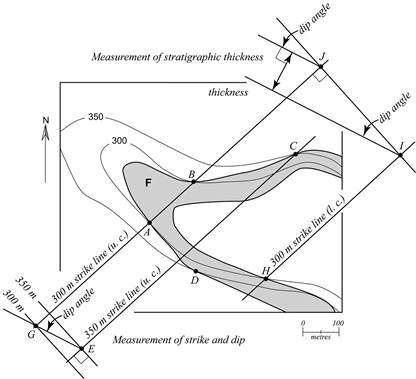
Figure 2.1. Measuring strike, dip, and thickness (modified from Fig. 1.4)
Measuring the dip requires a second strike line. A 350 m strike line is drawn parallel to the 300 m strike line where the 350 m contour line intersects the upper contact of bed F at point C. Ideally, point D should also fall on the 350 m strike line. The fact that it does not indicates that F is not a perfect plane. For our purposes, however, it is reasonable to approximate F as a perfect plane and to draw the strike lines parallel to each other.
The next step in measuring the dip is to draw two lines representing the elevations of the strike lines. The elevation lines must be perpendicular to the strike lines and must be spaced according to the map scale. In Figure 2.1, the 350 m and 300 m elevation lines are separated by 50 m on the scale of the map. Next, draw a diagonal line, EG, from the intersection of the highest elevation and strike line (point E) to the intersection of the lowest elevation and strike line (point G). The dip angle is measured down from the higher elevation line. The dip of bed F is 21°NW.
Lesson 2: Measuring Stratigraphic Thickness on a Geological Map
The technique for measuring stratigraphic thickness from a geologic map is illustrated in the upper right-hand corner of Figure 2.1. Measuring stratigraphic thickness requires two strike lines as well as the dip angle.
The 300 m strike line through points A and B will be used again. The second strike line must be for the same contour line, but the other contact of bed F. The 300 m strike line for the lower contact (l. c.) of bed F is drawn through point H, parallel to the other strike lines. (This is necessary because H is the only point in the map area where the 300 m contour line intersects the lower contact.)
The next step is to draw the line IJ perpendicular to the strike lines. Then, from point I and point J, draw in the dip angle. Once the dip angle is drawn in, you have lines representing the upper and lower contacts of bed F. This is like drawing a tiny segment of the geological cross-section in Figure 1.6 of Lab Unit 1. The stratigraphic thickness is the scaled distance measured perpendicular to the upper and lower contacts, just as it is in a geological cross-section.
Minimum Thickness
If a bed has only one contact in the map area, then the stratigraphic thickness cannot be measured. This is the case for beds C and G in the Greek Hills Map Area (Figure 1.4). However, we can place constraints on the minimum thickness of such a bed.
The process for determining minimum thickness is illustrated in Figure 2.2 below, which is a simplified version of Figure 1.4. For each of the beds C and G, it is possible to draw a strike line through one contact. With bed C, for example, the 400 m strike line can be drawn through points A and B on the lower contact. A second strike line is required to calculate thickness. In this case, we don¢t have the upper contact of bed C, but the 400 m contour line does continue into the NW corner of the map. Therefore, the next best thing to a true 400 m strike line through the upper contact is a second strike line that intersects the western side of the map where the 400 m contour goes out of the map area. From these measures we can proceed with the thickness calculation as before, but the result should be reported as a minimum thickness. For example, we would say that bed C is >92 m thick.
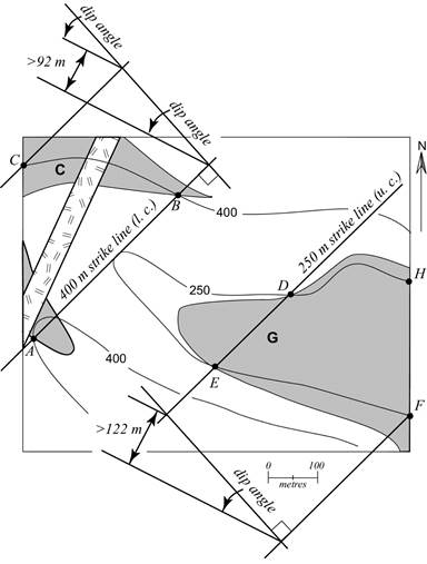
Figure 2.2. Measuring minimum thickness (modified from Figure 1.4)
The procedure for bed G is similar. The strike line we have is the 250 m strike line for the upper contact. There are two points where the 250 m contour line exits the east side of the map area. In this case, we would draw the second strike line through point F instead of through point H because the strike line through F will give the greater minimum thickness.
It is not uncommon for students who are new to measuring strike and dip and thickness from a geological map to confuse the two methods. Here is a quick summary for easy reference:
- When measuring strike and dip from a geological map, use one contact, and contour lines at two different elevations.
- When measuring thickness from a geological map, use one contour line, and upper and lower contacts.
Lesson 3: Constructing a Geological Map from Topographic and Strike and Dip Data
The trace of an outcrop can be plotted on a topographic map by a process that is almost like reversing the construction of a geological cross-section.
Reading Assignment
- Read Marshak & Mitra: “3-4. Calculation of Outcrop Trace from Attitude Data” (pp. 49-50)
Figure 3-8 in your lab textbook (p. 50) illustrates the layout of the problem, and the results of steps 1, 2, and 3. Figure 2.3a below shows the outcome of steps 4 and 5.
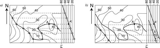
Figure 2.3
If we know the thickness of the bed and whether the point A is on the upper or lower contact of the bed, then we can repeat the steps to plot the second outcrop trace and map the entire bed. Figure 2.3b shows the outcome if A is on the lower contact of the bed and the bed has a stratigraphic thickness of 20 m.
Practice Exercise
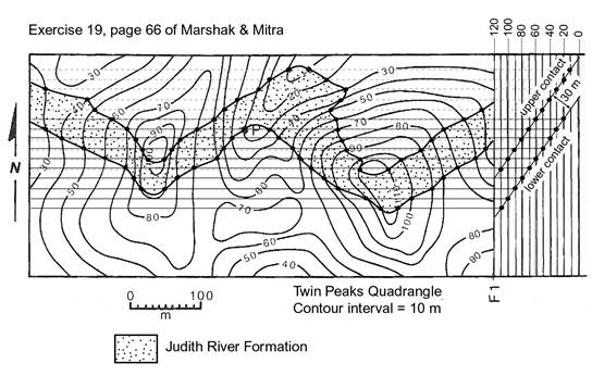
- For practice, do Exercise 19 (Marshak & Mitra, p. 66). You can find the solution at the end of this lab unit.
Assignment 2
You should now complete the lab portion of Assignment 2, which you can find in the assignment drop box. Assignment 2 is worth 6% of your final grade (theory portion: 2.5%; lab portion: 3.5%).
After you have completed Assignment 2 (both theory and lab portions), please submit this assignment to your tutor for grading. Please submit your assignment via the appropriate assignment drop box at your online course site. If you are unable to use the assignment drop box, please contact your tutor for an alternative submission method.
Solution to Practice Exercise