Geology 319 Structural Geology: The Architecture of Earth’s Continental Crust
Lab Unit 4
Solving Problems of Structural Geometry
Overview
In this lab unit, we will look at a number of problems that require us to determine information about the attitude of a geological structure. A stereonet is useful for problems that involve angles and directions, but in which distances and positions are not important. However, as depth and thickness do involve distances and positions, we must use descriptive geometry when distances and positions are significant. In some of the cases we will look at, trigonometry is also relatively easy to apply. In Lesson 1 you will learn how to find the distance to a planar feature and how to calculate stratigraphic thickness. Lesson 2 covers a variety of cases of apparent dip problems, and Lesson 3 covers the method for finding the orientation of a bed given the positions and elevations of three points on that plane.
Objectives
After working through this lab unit, you should be able to
- calculate the depth to a dipping surface and its thickness (descriptive geometry).
- solve apparent dip problems (descriptive geometry and stereonet) by
- calculating the apparent dip of a surface given its true dip.
- calculating the true dip of a surface given its apparent dip.
- calculating the true dip of a surface given two apparent dips.
- complete three-point problems (descriptive geometry) by
- calculating the attitude of a surface given elevations at three points, with two points at the same elevation.
- calculating the attitude of a surface given points at three different elevations.
Materials
- Basic Methods of Structural Geology by Marshak & Mitra
- stereonet
- several sheets of 8½″ × 11″ tracing paper
- several sheets of 8½″ × 11″ plain paper
- protractor
- ruler
- pencil
- eraser
- calculator
Lesson 1: Finding the Depth to Planar Geological Structures, and Stratigraphic Thickness
Finding Depth to a Plane
Imagine that you are a prospector looking for a mineral-bearing bed. You know that your main rival, Slimy Steve, has an outcrop of the bed on his land. You've also overheard him say that he was able to measure the strike and dip of the bed at the outcrop, and that it is oriented N12°W, 32°W. This is great news, because your property is down dip from the outcrop. You immediately rush out and book a drilling rig. If your property begins 100 m away from the outcrop, how deep must you drill vertically to encounter the top of the outcrop?
The situation is summarized in Figure 4.1 below. The outcrop is at A; the property line and the drill are at B, and the drill encounters the bed at C after drilling straight down. The angle BAC is the dip angle of the bed. By drawing the diagram to scale, we can determine the depth to the bed by measuring the distance BC. The result is 62.5 m.
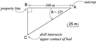
Figure 4.1. Finding the top of an outcrop
Alternatively, because the angle ABC is a right angle, there is also a straightforward trigonometric solution:
Practice Exercises
For practice, work through problems 4-1, 4-3a, and 4-3b (Marshak & Mitra, pp. 67-70). For 4-1, you may use the method of your choice. For 4-3a and 4-3b, use descriptive geometry. These exercises are for practice only. Do not submit them for grading.
Finding Stratigraphic Thickness
Given information about the depths of the upper and lower contacts of a dipping bed within a vertical drill hole, we can calculate the stratigraphic thickness (or true thickness) of the bed. As a prospector, this is something you would want to know, because it would help you decide whether the mineral deposit is large enough to justify the cost of recovering the minerals or too small to make you a profit.
If the drillers confirm your earlier calculations (finding the upper contact of the bed at 62.5 m depth) and then drill through the lower contact at 82.5 m, how thick is the bed?
Figure 4-12 (Marshak & Mitra, p. 77) illustrates this situation well. The lab text presents a trigonometric solution, but we will focus on descriptive geometry instead.
First, let's choose a scale that is convenient to work with. If you use too small a scale, small errors will have a larger effect on the result. We suggest using a scale of 1 cm = 10 m.
In Figure 4-12, the stippled region represents the bed, drawn at the appropriate dip. The distance TO is the difference in depth between lower and upper contacts (82.5 m − 62.5 m = 20 m). The angle ø is the dip angle (32°). The line segment BO forms a right angle with the line segment BT. In the space below, draw the triangle TOB using the dimensions appropriate for our problem. Then measure TB and use the scale to convert the distance in cm to a distance in m. You should find the true thickness of the bed to be 17 m.
Lesson 2: Apparent Dip Problems
The dip of a surface measured in a plane perpendicular to strike is called the true dip. Often, however, we encounter circumstances where a surface or bed is exposed along a plane that is not perpendicular to the strike. Figure 3-9 (Marshak & Mitra, p. 51) shows an example in which a dike is seen in a quarry wall, but the wall is not perpendicular to the strike of the dike. The dip that the dike appears to have when measured in the plane of the quarry wall is called the apparent dip.
In this section, we will look at three classes of problems concerning apparent dip:
- calculating the apparent dip of a surface given knowledge of the true dip,
- calculating the true dip of a surface given knowledge of its apparent dip, and
- calculating the true dip of a surface given measurements of its apparent dip in two different planes.
We will learn how to solve these problems using both descriptive geometry and the stereonet.
Apparent Dip Solutions Using Descriptive Geometry
Find Apparent Dip Given True Dip
Consider Figure 3-10a (Marshak & Mitra, p. 51). Imagine that the stippled plane is a hillside, and your favourite coffee shop is located at A. You and a friend are at the bottom of the hill, but you each decide on a different path to get up the hill to the coffee shop. You take the path C′A, and climb up at an angle ø, representative of the true dip of the hillside. Your friend takes the path B′A, and has an easier time because she is climbing at a lesser angle, δ, representing an apparent dip of the hillside. You can think of the descriptive geometry approach to solving all three classes of apparent dip problems as a matter of drawing right-angle triangles like CC′A and BB′A in Figure 3-10a, and making use of the following observations: both you and your friend experience the same elevation change (i.e., B′B = C′C), and you both end up at A.
Note: from here on, the symbol ⊥ will be used to indicate a line is “perpendicular to” or “at 90° to” another line.
Let's look at Exercise 6 (Marshak & Mitra, p. 61) to see how this works.
- The true attitude of a basalt dike is N40°E, 30°NW. What is the apparent dip of this dike as exposed in a vertical cliff face that trends N70°E?
Your goal is to draw the right-angle triangles CC′A: the triangle containing the true dip angle, and BB′A: the triangle containing the apparent dip angle. The attitude of the dike provides enough information to draw CC′A.
The first step is to draw N-S and E-W co-ordinate axes (see Fig. 4.2a, below). By analogy with Fig. 3-10a (Marshak & Mitra, p. 51) and our discussion above, the coffee shop (A) is at the origin.
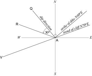
a) Drawing co-ordinate axes and the data you are given.
Draw AQ in the dip direction of the dike.
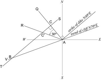
b) Complete the triangle CC′A containing the true dip angle.
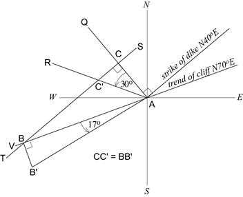
c) Complete the triangle BB′A containing the apparent dip angle.
Figure 4.2. Visualizing Exercise 6
Next, plot the information provided in the problem. Draw AQ in the dip direction of the dike. (In this example, the dip direction is 90°W from the strike direction of the dike.) Draw AR by measuring the true dip angle away from the dip direction. Also draw the trend of the cliff.
Complete the triangle containing the true dip angle by drawing the line ST ⊥ dip direction (Fig. 4.2b). The intersection of ST with AQ and AR are the points C and C′, respectively. Draw ST long enough to intersect the trend of the cliff. Where ST intersects AV is the point B.
It does not matter how long the segment CC′ is, as long as we draw a segment BB′ of the same length. (Remember that regardless of the path you take to get to the coffee shop, both you and your friend must achieve the same change in elevation.) Draw the segment BB′ ⊥ AV (Fig. 4.2c). Finally, complete the triangle BB′A by drawing the line B′A.
The apparent dip of the dike in the plane of the cliff is 17°SW.
Practice Exercises
For practice, do problem 3-7 (Marshak & Mitra, p. 55). Try to solve the problem yourself first before looking at the solution.
Find True Dip Given Apparent Dip
To find true dip when you are given the apparent dip, you will set up your solution as before, by drawing co-ordinate axes and the data you are given. The goal is still to draw the triangles BB′A and CC′A. The difference is that you will draw the triangles in a different order. You will complete the triangle BB′A, containing the apparent dip angle, first, and then complete the triangle CC′A containing the true dip angle.
Let's try Exercise 7 (Marshak & Mitra, p. 61):
- The strike of the bedding on the horizontal floor of a limestone quarry is N43°E. The apparent dip of the bedding in a north-south trending quarry wall is 32° toward the south. What is the true dip of the bedding?
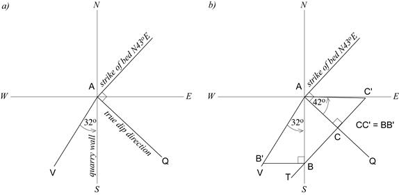
a) Draw co-ordinate axes and the data you are given.
Draw AQ in the dip direction of the bed.
b) Complete the triangle BB′A containing the apparent dip angle.
Draw TC′ such that TC′ ⊥ AQ and CC′ = BB′.
Figure 4.3. Exercise 7
After drawing N-S and E-W co-ordinate axes (Fig. 4.3a above), draw AQ in the dip direction of the bed. The bed is viewed in the plane of the quarry wall, so draw AV 32° away from the south axis. The south axis will form one side of BB′A.
Complete the triangle containing the apparent dip angle by drawing the line BB′ ⊥ quarry wall (Fig. 4.3b). Now draw the line TC′ such that:
- TC′ ⊥ AQ, and
- CC′ = BB′.
The true dip of the bed is 42°SE.
Practice Exercises
For practice, do problem 3-5 (Marshak & Mitra, p. 51). Try to solve the problem yourself first before looking at the solution.
Find True Dip Given Two Apparent Dips
In the previous two problems, you may have observed that the line connecting the two triangles always intersects the triangle containing the true dip in the same way. That is, it is always ⊥ true dip direction. This will also be true for the third class of apparent dip problems.
Going back to our earlier analogy, imagine that a second friend has joined you, and that all three of you are headed to the coffee shop. You each take a different straight-line path up the hill. You each make the same change in elevation, but you still take the steepest course, while your friends take easier climbs (see Fig. 3-11, Marshak & Mitra, p. 53). This time, however, you forget to note the angle at which you climbed. “No worries!” says one of your friends, “we took note of the angles we climbed, so we can calculate the angle you climbed.”
As you might have anticipated, the goal in this class of problem is to draw three right-angle triangles. Two of them, BB′A and DD′A will contain apparent dip angles. The third, CC′A will contain the true dip angle. You will draw BB′A and DD′A first, then CC′A.
Let's try the following exercise:
- An unconformity appears in two non-parallel roadcuts. In the first roadcut, trending N35°W, the unconformity has an apparent dip of 19°. In the second roadcut, trending N27°E, the unconformity has an apparent dip of 24°. What is the orientation of the unconformity?
Draw co-ordinate axes (Fig. 4.4a). Draw the lines AX and AV in the trend directions of the roadcuts (the apparent dip directions). Draw AY at 19° to AX, and AW at 24° to AV.
Next, complete the triangles BB′A and DD′A (Fig. 4.4b). Draw BB′ ⊥ AX. Draw DD′ such that DD′ ⊥ AV, and DD′ = BB′. Now draw the line ST to connect both triangles. ST connects the points C and D, and it is also the strike of the unconformity.
The true dip of a plane is perpendicular to its strike. This means that a line AC drawn ⊥ ST is oriented in the true dip direction (Fig. 4.4c). You can now finish the triangle CC′A by drawing the line AC′ such that CC′ = BB′ = DD′. The true dip angle is angle C′AC.
The orientation of the unconformity is N83°W, 25°N.
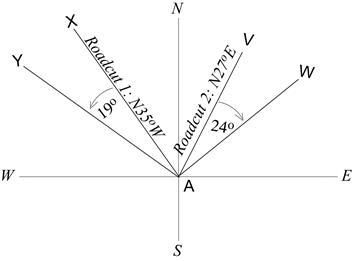
a) Draw co-ordinate axes and the data you are given.
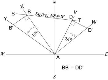
b) Complete the triangle BB′A by drawing the line BB′ ⊥ AX.
Complete DD′A by drawing DD′ such that DD′ ⊥ AV and DD′ = BB′.
Draw ST through B and D. ST is in the strike direction
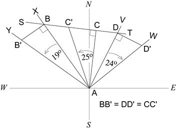
c) Complete the triangle CC′A containing the true dip angle.
Draw AC ⊥ ST and AC′ such that CC′ = BB′ = DD′.
Figure 4.4. Co-ordinates
Practice Exercises
For practice, do problem 3-6 (Marshak & Mitra, p. 51). Try to solve the problem yourself first before looking at the solution.
Apparent Dip Solutions Using the Stereonet
On the stereonet, apparent dip is plotted as a point. Recall from Lab Unit 3 that the orientation of a point is given by its trend and plunge. In apparent dip problems, the trend is the strike of the plane in which the apparent dip is being viewed. The plunge is the apparent dip angle.
Your goal in the first two classes of problems will be to draw two intersecting planes. One will represent the true orientation of the plane you are investigating. The other will represent the plane in which the apparent dip is being viewed. (Note that in the problems we do in Lab Unit 4, we will always consider cases in which this plane is vertical.) The apparent dip is at the intersection of these two planes.
In this section we will use the stereonet to re-do the three apparent dip problems we've just discussed. Instead of restating the problems verbatim, however, we will summarize the essential data of the problem by listing what information is given and what must be found. This is a good approach to any stereonet problem because it helps you to determine which details in the problem are important, and which are not. It also helps to clarify the goal of the problem.
Find Apparent Dip Given True Dip
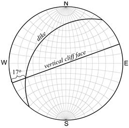
Figure 4.5. Finding apparent dip given true dip
Given:
- dike attitude N40°E, 30°NW
- vertical cliff trending N70°E
Find: apparent dip of dike in cliff face.
In this case, we have the orientation of the two planes. We need only plot them to find their point of intersection (Fig. 4.5).
The apparent dip is 17°SW.
Find True Dip Given Apparent Dip
Given:
- bed strike N43°E
- vertical quarry wall trending N-S
- apparent dip 32°S
Find: true dip of bed
In this problem, start by plotting the plane of the quarry wall and the apparent dip. Mark the strike of the bed using tick marks on the outside of the stereonet (Fig. 4.6a).
We know that the apparent dip is the point at which the planes of the bed and the quarry wall intersect. Therefore, rotate your overlay so that the tick mark indicating N43°E is at north on the stereonet (Fig. 4.6b). Find and trace the great circle that intersects the apparent dip. The dip of the plane you have just drawn is the true dip.
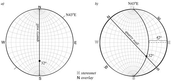
Figure 4.6. Finding true dip given apparent dip
Find True Dip Given Two Apparent Dips
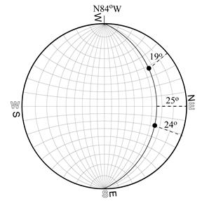
Figure 4.7. Finding true dip given two apparent dips
Given:
- apparent dip 19° along N35°W
- apparent dip 24° along N27°E
Find: orientation of unconformity
On the stereonet, two points define a plane. Plot the two apparent dips, then rotate your overlay until both points lie on the same great circle (Fig. 4.7).
The attitude of the unconformity is N84°W, 25°N.
Practice Exercises
For practice, do problems 3-5, 3-6, and 3-7 (Marshak & Mitra, pp. 51-55) over again using the stereonet. Ideally, you should get the same answer whether you use descriptive geometry or the stereonet. However, it is not uncommon to have a small difference of a few degrees. Nonetheless, it should be possible to keep your answers within ±3° of each other.
Lesson 3: Three-Point Method of Finding Strike and Dip
If you know the elevation of a planar surface at three separate locations, then you can calculate the strike and dip of that surface. We will look at two classes of three-point problems:
- three points, with two points at the same elevation, and
- three points with each point at a different elevation.
These problems are done using descriptive geometry. We cannot use a stereonet, because where the three points are located in space with respect to each other is important here.
Three Points with Two Points at the Same Elevation
You have done this kind of problem already. The only difference is that the last time you looked at the three points, there was a geologic map under them. In Lab Unit 2, you found the three points by looking for a place where a contour line intersected a particular contact at two points. You did this to find the strike of the bed. Then you looked for another contour line that intersected the same contact. You used the two strike lines to calculate the dip of the contact.
The method you are about to learn accomplishes the same thing: it gives you the strike and dip of a surface. But it has a major advantage. It can be used for a region that has not been mapped, but for which there are data from preliminary surveys or drill holes. Also, the contour interval does not restrict the elevations with which you can work.
Consider the scenario posed in exercise 1 (Marshak & Mitra, p. 60):
- A distinctive sandstone bed crops out at three localities in a corner of the Edmundsville Quadrangle. Outcrops A and B are on the 340-m contour line, and point C is on the 280-m contour line. Outcrop B is 400 m to the N40°E of outcrop A, and outcrop C is 240 m to the N20°W of outcrop A. Assuming that the sandstone bed is homoclinal, what is its strike and dip?
Note that the data for such problems may not always be presented in the same way. For example, you may be shown three points on a map instead. Regardless, the first goal is always the same: to draw a strike line by connecting the two points with the same elevation. For exercise 1, however, we will have to establish the locations of the points first.
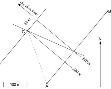
Figure 4.8. Exercise 1
Our data:
Outcrop |
Elevation |
Location |
A |
340 m |
|
B |
340 m |
400 m from A along N40°E |
C |
280 m |
240 m from A along N20°W |
Choose a convenient scale and draw points A, B, and C (Fig. 4.8).
Points A and B are at the same elevation, so the line that connects them is the 340 m strike line. C is at 280 m, so a line drawn through C that is parallel to AB is the 280 m strike line.
Now, find the dip. This procedure is the same as that in Lab Unit 2: draw two lines perpendicular to the 280 m and 340 m strike lines. Make the distance between these lines equal to the scaled elevation difference between 340 m and 280 m. In other words, the lines should be separated by 60 m, drawn to scale.
Draw a line connecting the 340 m elevation on the 340 m strike line to the 280 m elevation on the 280 m strike line.
The sandstone bed has an attitude of N40°E, 16°NW.
Practice Exercises
For practice, do problem 3-1 (Marshak & Mitra, p. 47). Try to solve the problem yourself first before looking at the solution.
Three Points, Each at a Different Elevation
As you might imagine, requiring that two of the data points have the same elevation could easily become inconvenient and restrictive. Fortunately, we only need to adjust our technique a little to turn the problem into one with two points at the same elevation.
Let's try exercise 3 (Marshak & Mitra, p. 60).
- Three wells have been drilled in Chatalkqua County by the Beanbody Coal Company in order to find the thick Queen Mother coal seam. To track the seam into the next county, the company geologists must know the strike and dip of the seam. The following data were obtained by the well-site crew. The wells were positioned at the corners of a square that is 500 m on a side. Two edges of this square trend north-south, and two edges trend east-west.
Well number |
Location |
Ground elevation |
Depth to top of coal |
459 |
NE |
730 m |
220 m |
460 |
NW |
850 m |
410 m |
461 |
SE |
760 m |
340 m |
In this exercise, we are given the ground elevation at the drill site and the depth to the top of the coal, but we need the elevation of the top of the coal seam. To get the elevation of the coal seam, subtract the depth to the top of the coal seam from the ground elevation. Using a convenient scale, draw the positions of the wells, and label each point with the elevation of the top of the coal seam (see Fig. 4.9).
The elevation changes from 510 m in the NE corner of the square to 420 m in the SE corner of the square. Therefore, somewhere along the eastern side of the square, there must also be a point at 440 m elevation a distance AE from the SE corner (inset, Fig. 4.9). If we can find that point, then we can draw the 440 m strike line using the well in the NW corner.
If we assume that the coal seam is homoclinal (i.e., that the dip angle of the coal seam remains constant), then we can use ratios to calculate the position of the 440 m elevation along the eastern side. The ratio of the total change in elevation to the distance between the NE and SE corners must be equal to the ratio of the change in elevation from 420 m to 440 m and the distance from the SE corner to the 440 m elevation. With reference to Figure 4.9 (inset),
Using a scale of 2 cm = 100 m, the elevation is 440 m, a distance of 2.2 cm north of the SE corner. Mark the 440 m elevation. Now you can proceed with the problem as though it were a three-point problem with two points at the same elevation. You can use either the 510 m elevation or the 420 m elevation with the two points at 440 m. In Figure 4.9, the 510 m elevation was used as the third point.
The Queen Mother coal seam has a strike of N52°W and a dip of 12°SW.
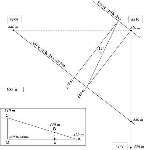
Figure 4.9. Exercise 3
Marshak & Mitra also illustrate graphical methods for doing three-point problems. The main difference is that the graphical method uses geometric constructions to find the location of the point with intermediate elevation.
Practice Exercises
For practice, do problem 3-3 (Marshak & Mitra, p. 49).
Assignment 4
You should now complete the lab portion of Assignment 4, which you can find in the assignment drop box. Assignment 4 is worth 6% of your final grade (theory portion: 2.5%; lab portion: 3.5%).
After you have completed Assignment 4, please submit this assignment (both theory and lab portions) to your tutor for grading. Please submit your assignment via the appropriate assignment drop box at your online course site. If you are unable to use the assignment drop box, please contact your tutor for an alternative submission method.